Other Parts Discussed in Thread: OPA1656, OPA1622, OPA1662, BUF634
Hello,
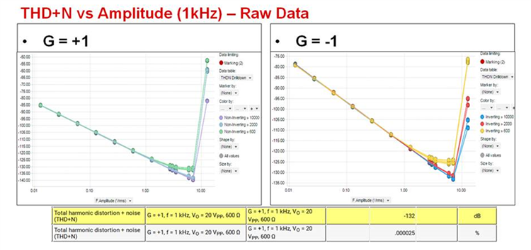
Referreing to fig. 6-6 in the OPA2210 Datasheet SBOS924G, it seems rather strange that the THD+N is less in the non-inverting configuration, when both inputs are swinging with the input signal, relative to when they are at virtual zero in the inverting configuration.
Can you verify that these plots are correct and not a mislabeling of traces?
Second question: can you update the graph with different output loads, e.g. 2k and 10k (+100pF in parallel)?
Thank you!