Hello,
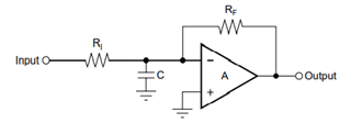
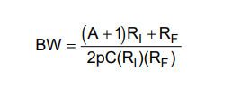
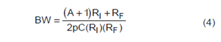
in a hardware design i am using the VCA2612 with two differential input signals. The VCA2612 provides a compensation when using active Feedback. The value for the capacitor is calculated with Equation 4 in the datasheet (see below).
The Question for me is where i have to place it for both channels (A and B)?
Is it between pin 10 (COMP1A) and 11 (COMP2A) for channel A and between pin 27 (COMP1B) and pin 26 (COMP2B) for channel B?
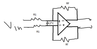
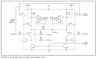
Or should I use Figure 4 as a guide and place the capacitor between pin 11 (COMP2A) and pin 16 (LNP_IN_PA) for the positive input and between pin 10 (COMP1A) and pin 12 (LNP_IN_NA) for the negative input of channel A?
In this case there is to place the capacitor for Channel B between pin 26 (COMP2B) and pin 21 (LNP_IN_PB) for the positve input and between pin 27 (COMP1B) and pin 25 (LNB_IN_NB) for the negative input, right?
Thank you in advance.