This thread has been locked.

If you have a related question, please click the "Ask a related question" button in the top right corner. The newly created question will be automatically linked to this question.

OPA388: lower drift amplifier options

Part Number: OPA388
Other Parts Discussed in Thread: OPA2277, , OPA2317, INA317, OPA2388, THP210, OPA2387, INA333, OPA2333, OPA227, OPA627, OPA210, OPA2206, OPA192

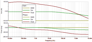
Hi, my customer is looking for the least noisy and drifty OPAMs . Typical gain at low frequency (0.1 to 1 Hz) is in the range of 100 – 500k gain. The gain is dropping with frequency and crossing unity at about 300 – 1000 Hz. Noise is not important at 1KHz.

The system runs on a 3V rail. Another issue is potential ground loops due to relatively long cables; the same shift in the ground level (say, 1 mV) now is almost 7 times more visible (20V dynamic span vs. 3 V)

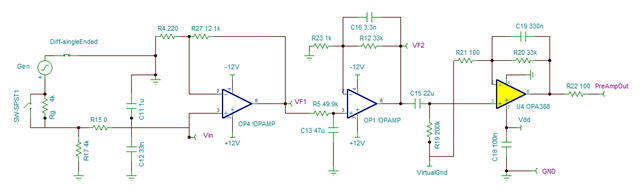
They have created 3V version preamplifier which works satisfactory, using OPA2277 or ISL28134 as the first amplifier.

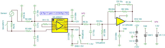
Now, they are using OPA388 but drift is still about 2-3 times more than they can tolerate.

What OPAM can you suggest, lowest drift, lowest input offset voltage?

  • Hi Collin,

    Could you share the schematic with us? I want to know what type of application this is. There are several things that are not clear. Here is summarized op amp requirements. 

    1. Typical gain at low frequency (0.1 to 1 Hz) is in the range of 100 – 500k gain.--> Are you talking about the Aol gain requirements. 

    2. The BW of the closed loop op amp is <1kHz. 

    3. Voltage spectral noise density is not an important factor.

    4. Very high common mode noise presented at op amp input terminals.  

    5. Preamplifier (OPA2277 or ISL28134)  helps to attenuate the input noise...

    6. OPA388 op amp after preamplifier is still seen 2X-3X in drift (thermal drift?) in the application. 

    OPA2388 is an exceptional high performance op amp. If it does not meet the requirements, OPA2317, OPA2333, OPA2387 are likely not going to do better either. Have you considered differential input op amp (THP210) and/or instrumentation amplifier for the application (e.g., INA333, INA317 etc.)?

    I'd like to understand the application better before I make a recommendation. 

    BTW, have you tried shielded the input cable at the analog front end of the op amp?. It may help to reduce noise coupling into op amp input terminal, to guard against EMI/RFI interferences, and improve radiated and conducted susceptibility from the operating environment. 

    Best,

    Raymond


  • Hi Collin,

    I think your customer suffers from the Seebeck effect.

    What is the source of the circuit and what is the source impedance?

    Why is there a ground loop at the input? And why are long cables involved?

    Kai

  • Hello,

    I am the "customer" :-)

    This amplifier preconditions signal from a sensor to be used for feedback control. Its desired transfer function is shown below.

    Sensor essentially is a coil, has DC resistance of 4k; it creates voltage if shaken

    RE: ground loops - sorry for confusion; it is not related to drift itself; but combined drift plus ground loop offset could saturate output.
    I only pointed out that previous generation amplifier used +/-10V signal range, and the new one has to use 0 to +3 V range;

    Both get converted to digital value by 16 bit ADCs; it means that IF there is a ground loop error (due to the same current in ground wire), this same extra, say, 1 mV could create almost seven times (=20/3) larger error to digitized output.

    RE: Seebeck effect - the temperature around amplifier and sensor is rather stable, and we minimize air flow("closed box") which affects drift. Older amplifier at the same setup has 3x-5x less drift.

    RE: shielding / EMF: whole amplifier (on the right) is shielded, on the bottom of the board is solid copper. The cables to sensors are shielded coaxial type.

    RE: TF of amplifier: shown new amplifier; the old amplifier has about 3x more gain

    RE schematic: bipolar amplifiers [generally] have better characteristics than unipolar; that's why I use bipolar as the first (and 2nd in 3-stages)

    I tried 3-stages and 2-stages amplifiers,

    The last stage must be DC isolated to create 1.5V offset, the DC-blocking capacitor is about 20 uF.

    In 3-stages topology,  for the first stages I tried OPA227, LT1007, OPA627 and similar

    NOTE older amplifier with output of +/-10V has similar 3-stage topology; first amplifier is OPA227

    2-stages with instrumentation amplifier; as first stage, I also tried single-ended topology with OPA388, OPA210, ISL28134

    So far, only the OPA210 has shown about 20% improvement in drift.

    these 3-stages and 2-stages designs have about the same drift 

    Typical electrical drift (about 250 counts) is shown below: sensor is removed, note the input has about 2K resistance to ground and 4K resistor across sensor input

    If the amplifier is used in a real system in a feedback loop, the drift is increased to about 1500-3000 ADC counts.

    However, the older amplifier with output of +/-10V ( 3-stage topology) at similar setup has drift about 300-500 ADC counts

    What I suspect is the capacitors used for filtering (and DC-block ) could be causing the drift; when input is shorted, some ceramic caps had shown longer settling time coming to 1.5V and more drift;

    I only use 50V ceramic caps +-10% (X7R) but still, some are much better in settling; I tried film PPS caps and saw some drift improvement (maybe 20% better).

    Unfortunately film caps are much larger.

    I am somewhat reluctant to reduce capacitance and increase resistance because it will cause more Johnson's noise; but may try this.
    Again, older 10V output amplifier with 3-stage topology has about 3-5x less drift.

    Igor

  • Hi Igor,

    Auto-zero op amps such as the OPA388 typically don't perform to their best when very high input or feedback resistances provide the path for their dc input bias currents. That is because the charge transfer currents associated with the input switching, gets converted to voltage noise as it flows through those high resistances and appears at the op amp output.

    Usually we find that the input current spike related noise is much reduced when the circuit resistances are kept well below 10 kilohms and the circuit is balanced in terms of the resistance and capacitances the inputs look into. The U1, OPA388 TINA circuit may be exhibiting this issue. It is interesting that the OPA2206 is going about the best of the op amps. It uses a non-switching op amp design and therefore, doesn't exhibit the input current charge transfer behavior. The ISL28134 is not produced by TI, but appears to be an auto-zero op amp.

    The OPA192 achieves very low offset and drift using TI's e-trim technology and doesn't employ auto-zero switching techniques. It should be much less sensitive to the high-value resistors in the circuit because it is a CMOS op amp having extremely high input impedance. I suggest trying one in your circuit and see what level of performance it achieves. It would be interesting see if it is better.

     https://www.ti.com/lit/ds/symlink/opa192.pdf

    Regards, Thomas

    Precision Amplifiers Applications Engineering

  • Thanks, Kai,

    Very interesting in depth overview! Will try your tips...