This thread has been locked.

If you have a related question, please click the "Ask a related question" button in the top right corner. The newly created question will be automatically linked to this question.

THS4631DGNEVM: Measuring DC potentials generated by a magnetic field?

Part Number: THS4631DGNEVM
Other Parts Discussed in Thread: THS4631, OPA2210, OPA2182, OPA2192, DUAL-DIYAMP-EVM

Hello Guys,

Good day.

I see that THS4631DGNEVM  is a Transimpedance amplifier and act as front-end amplifiers for optical sensors. However our customer is considering to use this in measuring DC potentials generated by cutting through a magnetic field. Is this possible with this EVM?

They have a coil of AWG 36 magnet wire that is about one mile long (2.43 k ohms), and wants to perform this DC measurement.

Thanks in advance!

Art

  • Hello Art,

    The THS4631 isn't set in a trans-impedance configuration by default, it is a regular FET-input amplifier. Could you provide more details on how the customer planning on using the THS4631 in this application?

    Best,

    Hasan Babiker

  • Hello Hasan,

    According to our customer he will be sensing d.c. voltages in the microvolt range. The requirement for an input impedance for the device is equal to or greater than 10 megohms indicates that he needs to draw as little current as possible when making the measurements, though the instrument amplifier itself will use this miniscule current to make the measurement.

    Correction, he is not using a device to measure a magnetic field directly (a hall effect device).
    He have used Fluke Multimeter with a 10 megohm input impedance on the d.c., 200 mv range, but his meter is not sensitive enough to read in the microvolt range. It indicates that he is reading something, but the potentials are too small for his multimeter. That is why he is looking for a Texas Instrument amplifier.
    Thanks!
    Art
  • Hey Art,

    Thanks for the clarification, what is the customer's needed bandwidth? and what gain are they trying to achieve?

    Best,

    Hasan Babiker

  • Hi Hasan,

    Good day.

    I will notify customer of the additional inquiries.

    Also, I might direct the customer to this thread directly so that he would be able to explain his use case better.

    Thanks!

    Art

  • Sounds good, feel free to have customer either respond to this thread or open a new one.

    Best,

    Hasan Babiker

  • Hasan,

    I need to make a measurement in the d.c. microvolt range across a d.c. resistance of 2.43 K ohms at an amplification of 10,000.

    Will the THS4631SGNEVN, Amplifier IC, Development tool work?

    The d.c. resistance is a coil of AWG #36 copper magnet wire in a coil rectangular form of 2.5' x 2.5".

    I need an input impedance for the Amplifier IC of at least 10 megohms.

    The d.c. potentials are being generated by the coil passing through a magnetic field.

    The readings are a pure d.c. There is no a.c. component.

    I  need the best amplification I can get for my application.

    Darden

  • Hi Darden,

    is 2430Ohm the resistance of coil?

    Do you know the inductance of coil? Is it an air coil? Or does it contain a core?

    Kai

  • Kai,                                                                                                                  29 August 2020

    1. Resistance of the coil = 2430 ohms
    2. Approximate L (inductance of coil) = 174.6 microhenries
    3. Core = water

    Comments: These figures are approximate. The formula I used for determining inductance was for a circular coil. The actual one is flattened to a rectangular shape (23-5/8" x 1-1/16"). 

    I multiplied the sum of these by 2 to give me the circumference of a circle and derived the radius from the formula d = C/π. Whether a "squashed" circle would have the same inductance, I do not know. Also, the core I am using is water (H2O). The formula I used is for air:  L (µh) = a2n2 / 9a + 10b, where L = Inductance in microhenries, a = coil radius in inches, b- coil length in inches, n = number of turns.


    If you need a more accurate estimate for inductance, the National Instruments 6-1/2 Digit DMM, NI USB-4065, can measure inductance directly. I do not have access to one right now, but I could make arrangements for that measurement, if needed.


    Darden

  • Hi Darden,

    I think the OPA2210 is a much better choice than the THS4631.

    Kai

  • Hello,

    I agree the THS4631 may not be the best choice. Max Input offset voltage is set at around 500uV for this device. Since bandwidth is not a concern, a lower bandwidth FET-input precision amplifier will work better in this case. The issue with the OPA2210 is it's differential resistance of 400 kohms. Looping in the precision amplifier team to help recommend a device for this application.

    Best,

    Hasan Babiker

  • Thank you, Hasan.

    Anxiously awaiting you reply.

    Darden

  • Hello Hasan,

    Since this is a microvolt level dc measurement application it will likely require a very high precision op amp with as little of 1/f noise as possible. If the gain set resistance for the op amp are kept reasonably (<10 kilohm), then an auto-zero op amp may provide the highest performance. 

    The OPA2182 is our newest Precison Amplifiers auto-zero op amp having a maximum voltage offset of ±4 µV, for TA = –40°C to 125°C, and typical input voltage noise density of 5.7 nV/√Hz (10 Hz, 100 Hz, 1 kHZ) and typical input voltage noise of 18 nVRMS from f = 0.1 Hz to 10 Hz. The auto-zero op amp architecture cancels the 1/f noise that non-switching op amp architectures have. Its differential input impedance is 0.1 GΩ || 3.7 pF, which is a decade above the 10 Megohm required for the application. Here's a link to the OPA2182 datasheet:

    https://www.ti.com/lit/ds/symlink/opa2182.pdf

    It is mentioned the gain needs to be 10 kV/V, which is very, very high. I do not recommend trying to achieve that all the gain in one stage. Although the open-loop gain of the OPA2182 op amps is very high, the gain error would be quite large with a closed-loop gain of 10 kV/V. The OPA2182 is dual op amp and the gain could easily be shared between the two op amps arranged in two stages. 

    Here is a new Applications Note we just published on the subject of cascaded op amp gain stages:

    https://www.ti.com/lit/an/sboa356/sboa356.pdf

    If you for some reason don't want to try the auto-zero op amp approach, then have a look at one of our e-Trim precision op amps - OPA2192:

    https://www.ti.com/lit/ds/symlink/opa192.pdf

    Regards, Thomas

    Precision Amplifiers Applications Engineering

  • Thank you, Thomas.

    I am looking at the TI DIYAMP-SOIC-EVM evaluation module  to use as a platform for the device.

    Will that work as far as having room for components if I cascade the OPA2122 ?

    Darden

  • Hi Darden,

    first, thank you for giving the inductance of coil :-)

    Amplifying signals in the µV range is not an easy thing. Are you familiar with the construction of electronic circuits?

    Kai

  • Yes I am Kai.

    Darden

  • Hello Darden,

    There is the DUAL-DIYAMP-EVM which is designed for dual op amps such as the OPA2182, in an 8-pin package. Since the DIY PC board is designed for 12 different circuit configurations it is likely you will be able to use it for your OPA2182 amplifier tests. Here's a link the DUAL-DIYAMP-EVM:

    https://www.ti.com/lit/ug/sbou193/sbou193.pdf

    Have a look at the different amplifier configurations and see if it will accommodate your two stage design. I suspect it will be usable.

    Regards, Thomas

    Precision Amplifiers Applications Engineering

  • Thank you, Thomas,

    and thanks, everyone, for your help.

    Darden

  • HI Darden,

    Good luck with your microvolt amplifier circuit. Glad we could assist.

    Regards, Thomas

    Precision Amplifiers Applications Engineering

  • Hi Darden,

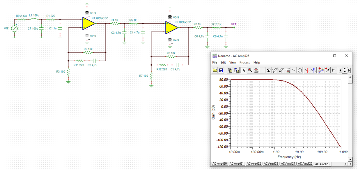
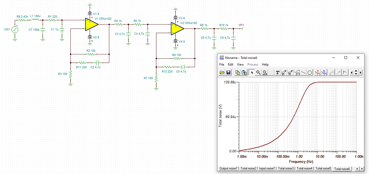
    I would give this circuit a try:

    darden_opa2182.TSC

    Kai

  • Thank you, Kai.

    Are the 1 micro farad and above electrolytic capacitors?

    If so, can tantalum capacitors be used?

    Also, what voltage rating should I use for them, e.g. 20 vdc?

    Would 0.1 watts be a satisfactory rating for the resistors?

    Also, there are many options for inductor L1, 180 micro henries

    (shielded is one of them).

    Darden

  • Hi Darden,

    some comments on the circuit:

    1. R9, L1 and C7 is the equivalent circuit of your sensor. C7 is estimated, as it's actual value is not of interest because of the low bandwidth of your circuit.

    2. R1 and C1 form a passive low pass filter. Always a good idea at the input of a first stage OPAmp. R1 (and R3) is about one tenth of R9 so that its additional resistor noise will not play any relevant role.

    3. Both OPAmp stages have a gain of 101 each which makes about 10,000 together.

    4. You see a lot of low pass filtering in the circuit, e.g. C2, C3, C4,... The idea is to heavily reduce the gain at the technical frequncies of 50Hz and 60Hz because even the least 60Hz hum coming from a mains transformer or else would ruin your measurement.

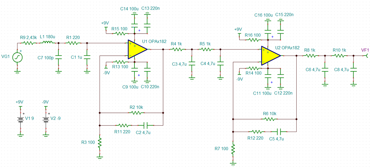
    5. There's no power supply filtering for the OPAmp shown. I recommend a RC-filter consisting of 100R and 100µF/16V aluminium electrolytic paralleled by 100...470n X7R at each power supply pin of OPAmp. This not only hepls to decrease the HF noise but is also good for supply voltage sequencing.

    6. To avoid any hazzle with ground loops I would supply the circuit with two 9V batteries.

    7. Only components of highest performance should be used in this circuit. Don't use thick film resistors or carbon film. Only use highest precision thin film resistors. I would take 0.1% resistors with 25ppm/K temperature coefficient. Then you can be sure that the right film material is used in the resistor.

    As the involved signal voltages are ultra low, heat dissipation is no issue here. Having said this, I wouldn't take all too tiny resistors. 0805 is appropriate.

    8. Caps are especially critical here because of the "microphonic" effect. Caps produce a voltage when they are touched or twisted. When amplyfing µV signals this microphonic effect would be a disaster. As a rule of thumb the higher the dielectric number of cap the higher the microphonic effect. So in the signal path X7R ceramic and such must be omitted. NP0 is ok but hard to find 4µ7 in NP0 :-)

    I would take polyester film caps like this:

    Electrolytic caps can generate flicker noise because of their special dielectric material and should also be avoided in the signal path here.

    Some additional hints:

    a. Solder joints form unwanted thermocouples of many µV/K. Usually, there voltages are back to back in series and cancel each other. But when the solder joints are brought to different temperatures the unwanted thermocouple voltages can ruin your measurement. So I would use a massive aluminium enclosure allowing an even thermalization of your whole electronics.

    b. Don't use any metall showing ferromagnetism for the enclosure and shieldings. They can hugely amplify foreign and unwanted magnetic fields. They can just do the oppsosite of shielding but transport foreign magnetic fields to places where you don't want to have them. Only aluminium and copper should be used. Prefer unalloyed soft aluminium over duraluminium.

    c. The whole circuit must be stiff and rigid. No cable and now wire should be allowed to move. This is especially vaild for the sensor cable. Cable movement can cause noise by changing its cable capacitance and due to frictional movement of the shield over the insulation material.

    d. You will need to place the sensor itself within the shield (Faraday cage). Thin aluminium foil (as thin as kitchen foil) will give a proper electrostatic shield without damping the magnetic fields in the DC frequency range of your application all too much. (I have shielded my Stratocaster with kitchen foil and cannot here any dampening of the higher frequencies :-))

    Kai 

  • Thank you, Kai, for all your help :-)

    Darden

  • Kai,

    I have a question concerning Item # 5 in your latest message:

    1. What is the value of 100R?
    2. Is 100R in series with the 100uf, 16V aluminum electrolytic?
    3. Is the 100-470nf X7R ceramic capacitor in parallel with both 100R and the 100uf electrolytic, or just parallel with the 100uf electrolytic?
    4. Can a 9v, battery operated regulator IC be used in place of the RC filter? 

    Also, I need an evaluation module for for the OPA2122. The collection of evaluation modules on the PC Board that was sent me does not have a dual power supply circuit..

    I also need room to add additional components to the schematics you sent  me. Do you have any suggestions?

    Darden

  • Hi Darden,

    for the 100R resistor 0204 package is ok. The supply filtering components should look like this:

    To have more room for all the components, I would take two OPA2182 and use only one half of each. Connect the unused OPAmp as voltage follower (+input to signal ground and -input to output of OPAmp).

    The OPA2182 allows input voltages down to the negative supply voltage, yes even 0.1V below the negative supply voltage. From this it seems to be possible to power the OPA2182 single supply. Unfortunately, the output voltage of OPA2182 cannot go negative. And the usual trick in single supply circuits to generate an auxiliary signal ground at middsupply will not work here, because the least supply noise - even with sophisticated filtering - will be directly injected into the signal path and will ruin your measurement.

    So only a bipolar supply voltage powering should be used here. Then the circuit can profit from the extreme proper supply voltage rejection of OPA2182 and no supply noise will be directly coupled into the signal path.

    Powering the circuit from a voltage regulator is possible but critical. It would do it in a second step. First I would make the circuit run with batteries.

    Kai

  • Hi Kai,

    In using the Faraday cage, can I use the cage as a signal ground for the Operational Amplified circuits or do the two need to be isolated?

    In other words, can I mount the 50 ohm sma coax connector on a solid copper Faraday cage using the cage as a ground, or

    do I have to isolate the cage from the OP Amp circuit and use an earth ground on the cage?

    Darden

  • Hi Darden,

    there's no simple answer. It depends on how you shield and at which places the shield is connected to signal ground. And we should take the fact into account that we are dealing with µV-Signals :-)

    I would use this shielding scheme:

    You see three shields, one shield (pink) covering the components of first amplifier stage (including the sensor), another shield (blue) covering the components of second amplifier stage and, finally, a third shield (red) covering the whole circuit including both individual shields. Look where exactly the three shields are connected to the individual signal grounds. Take care that the three shields should not touch each other.

    I would create two different local signal grounds, a pink one and a blue one. All components of the first amplifier stage (including the sensor) or, by other words, all components covered by the pink shield should be connected to the pink signal ground and all components of the second amplifier stage (i.e. all components covered by the blue shield) should be connected to the blue signal ground.

    As the signal frequency bandwidth is very low, the pink and blue shields need not necessarily to form 100%ly closed housings, provided there's no strong HF radiation in your application (cellphone, etc.). Some sheets of metal might be enough then. But don't allow them to form loop areas by connecting them to signal ground at different places. Star point signal grounding by using a pink signal ground star point and a blue signal ground star point would be optimal here. This is what I meant by "local signal grounds".

    Your 50R SMA connector can be connected to the red shield, right where it is connected to the red signal ground. This helps to use the cable shield as an extension of the red Faraday cage which is the best cure against cellphone radiation.

    Kai

  • Thank you, Kai.

    When I finish the assembly, I would like to send photos of it to you.

    Darden

  • I'd be glad to :-)

    Kai

  • Hi Darden,

    Do you think that this e2e can be closed now while you work on your design and testing? If you need more assistance later you can always open a new e2e inquiry.

    Regards, Thomas

    Precision Amplifiers Applications Engineering