This thread has been locked.

If you have a related question, please click the "Ask a related question" button in the top right corner. The newly created question will be automatically linked to this question.

LMC6082: Photodiode detector amplifier

Part Number: LMC6082

Hi,

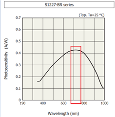
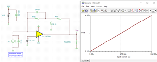
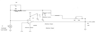
Attached circuit diagram of LMC6082 Amplifier used in my design below. Please explain how it works and operation for the better understanding. Is this configured as Photoconductive mode (Converts Photocurrent to output voltage) like Trans Impedance amplifier? How much Gain will be set using this circuit, Is it possible to explain with min and max values of Input Current/ Voltage and Output Current/ Voltage? I am not expertise in this topic so expecting the detailed explanation. Thanks in advance.

Regards,

Karthick V

  • Well Karthick, you are in luck - this transimpedance design with tee network in feedback (1st in Graeme's 1996 book) showed up recently here - 

    https://www.ti.com/lit/an/sboa284/sboa284.pdf

  • Hi Karthick,

    Enclosed is the TIA application note that you can follow, design and adjust the gain of the circuit. 

    https://www.ti.com/lit/ug/tidu535/tidu535.pdf?ts=1624462940997&ref_url=https%253A%252F%252Fwww.google.com%252F

    I am going to explain what is not so obvious in your design. 

    Here is the photodiode in your circuit, see the link below. This is a large area photodiode sensor with red wavelength of 720nm is most sensitive, see the plot.  The current generated from the photodiode is a function of light intensity and light wavelength.  So you may have to adjust the gain of TIA circuit accordingly depending on your sensing application. 

    https://www.hamamatsu.com/us/en/product/type/S1227-1010BR/index.html

    Since your photodiode is large in area, according to the plot above, you really do not need implement Tee network in the TIA design. I am only able to simulate the current condition from 1uA to 950uA with 5V single supply rail with Gain resistor of 5kΩ. 

    The Tee network may be implemented if the circuit is required a large MΩ or GΩ gain resistors in TIA circuit. Your photo sensor will generate too much current due to its area and light sensitivity, unless the application is operating under extremely low light conditions or with narrow band optical filter + aperture etc.. Even your light source is operating <400nm or >780nm NIR region, you still have approx. 0.1A/W in light sensitivity.

    It is very likely that your light source is red in color, otherwise you may select other wavelength response sensor curve per the detection application. 

    If you put your circuit together as is and the op amp's output will likely saturate at 5V. Enclosed is a simulation example that you can see it for yourself. 

    LMC6082 TIA 06232021.TSC

    While I am trying to explain how a Tee network works, Michael is replied with a great application note, so please study the article. 

    If you have additional questions, please let us know. 

    Best,

    Raymond

  • Hi Karthick,

    the circuit looks a bit trashy to me or at least incomplete: If RA8 is set to 0R, the output of OPAmp is short-circuited to signal ground by the way too small 44R resistor RA5. So either RA5 should be way bigger than 44R or a resistor in series to RA8 is missing Relaxed

    Kai