Other Parts Discussed in Thread: PGA309, XTR117
To whom it may concern,
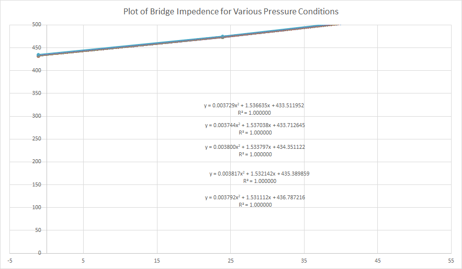
We are using the PGA309-EVM to confirm the use of the PGA309 in our application. We are currently using the temperature coefficient of the strain sensor bridge for temperature compensation. We are using a 40.2 ohm high side fixed resistor and our bridge is 400 to 500 ohms. We can get the sensor emulator to function well with raw data and achieve good calibrations with it.
Our problem is when we try to implement The "Enter Rt Characteristics" method of creating the emulator file. Specifically how to derive the "TC1 Bridge" and "TC2 Bridge" values. Can you provide instructions and the formula used to derive this?
I have attached some the model files just created and a spreadsheet with values for the bridge also some calculations.
Thanks for your time!
Joe
210720-Question on setup for RT positive method.xlsx
[Filenames]
Pre-Cal Filename=Test-121313-precal.txt
Sensor Emulator Filename=Test-121313-Sensor.csv
[Misc]
Comments=test
Serial No=1
Model No=0
Model ID=test
Use Sensor Emulator=TRUE
[PGA309_Settings]
Numb Reg=3
Poly Order=2
Output Mode=1
Vout_High_Target=4.500000
Iout_High_Target=0.000000
Iout_Low_Target=0.000000
Vout_Low_Target=0.500000
Vs=5.000000
Vref=4.096000
Calibrate Nonlin=FALSE
Reg0=0
Reg1=0
Reg2=0
Reg3=1280
Reg4=0
Reg5=0
Reg6=5147
Reg7=0
Reg8=0
Temp0=-1.111000
Temp1=23.889000
Temp2=54.444000