This thread has been locked.

If you have a related question, please click the "Ask a related question" button in the top right corner. The newly created question will be automatically linked to this question.

TL072: Schematic Check

Part Number: TL072

Hi, expert

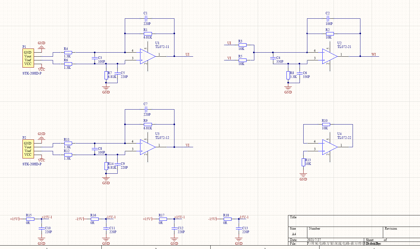
My customer is using TL072 to do current sampling in inverter, they add U current and I current up to W current. The power supply is +/-15V, and input signal frequency is less than 50Hz.

They found there are random high output pulse on WI even when UI and VI is several mV, could you please help check if there are some design flaws in their schematic? Thanks.

Best Regards.

Chen

  • Hi Chen,

    remove C3, C4 and C8. They will erode the phase margin and destabilize the OPAmps.

    Replace R8 by a short circuit and remove C6. Replace R10 by a short circuit. An input bias current canceling scheme is not necessary with an OPAmp having JFETs at the inputs.

    If C10...13 shall be the supply voltage decoupling caps, increase them to 100nF.

    Kai

  • Hi Chen,

    I agree with Kai's recommendations. If this is a high switching current design, it is important to ensure there is a proper PCB layout. If Kai's recommendations don't help the problem, please post scope shots of the issues. Please include scope shots of the input signals, output signals, and power supplies.

    Thank you,

    Tim Claycomb