This thread has been locked.

If you have a related question, please click the "Ask a related question" button in the top right corner. The newly created question will be automatically linked to this question.

LM339: output capacitor / schematic review

Genius 16485 points
Part Number: LM339

Hi all

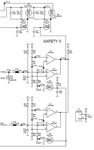
My customer has implemented a window comparator circuit as illustrated in the below schematic with the LM339.

Under normal operation the output of U7 is high. If a fault condition occurs the output of U7 is pulled low.

For one PCB they find the output of U7 is stuck low regardless of the input, replacing the IC fixes the problem.

Do you see anything wrong with this circuit ?

Do you see a problem with e.g. C21 10nF capacitor at the output of U7 ?

Best regards

Ueli

  • Hello Ueli,

    I do not see anything inherently wrong with the circuit, but that does not rule out layout issues or electrical transient problems not visible in a schematic.

    The input range for the LM339 is 0 to 3V on a 5V supply. The reference voltage is about 2V, which is fine. For the output to "stick" low, then BOTH inputs would have to be above 3V.

    I see some fusable links on the RTD's - so I assume this is not a "friendly" environment and that there are high voltages/currents elsewhere in the circuit.

    Are you seeing this on many boards? Or just the one device? Is it repeatable? Did the LM339 get warm? Is the output being held low, or "blown" low (what is the resistance measurement from the output to GND pin with no power?).

    A capacitor on the output should not be an issue, but we do not recommend adding large capacitors to the output to "filter", and instead encourage adding hysteresis (though that is difficult on an "OR'ed" output).

  • Hi Paul

    Thank you for the quick reply.

    The customer is seeing this only for one device and the output doesn't show a short when desoldered and measured with no power.

    Another test the customer didn't yet do is an A-B-A swap, meaning to test if the fault really follows the device.

    So there are additional tests the customer can do to investigate the root cause.

    Best regards

    Ueli

  • Sounds good Ueli

    we will wait for additional feedback.

    Chuck

  • Hi Paul

    The investigation from the customer wasn't conclusive, meaning they were not able to pinpoint the exact root cause.

    Your comments as to the capacitor are appreciated by the customer.

    So no further action from your side required.

    Best regards

    Ueli

    -------------------------

    PS: FL31 / FL32 does stand for ferrite beads and not fusible links

  • Hi Ueli,

    in my opinion it's very bad design practise to directly discharge a cap with the output of an comparator, without any current limiting, especially if this cap is not directly referenced to the ground pin of comparator. By this an enormous discharging current spike will run across complex ground impedances resulting in a huge ground bounce, not only outside the comparator but even inside the comparator itself, directly on the die. This can cause instability and even latch-up.

    See this huge 82mA current spike and the dramatical decrease of discharging current after the introduce of 1k current limiting resistor:

    ueli_lm339.TSC

    In any case, I would limit the discharging current by a suited resistor mounted directly at each comparator output. Also, move C21 close to the two comparators, move both comparators close to each other and use a solid ground plane.

    Also, mount a current limiting resistor in the charging and discharging path of C20 and C22 as well.

    Kai

  • Thanks Ueli for following up and to Kai for your input.

    Chuck