This thread has been locked.

If you have a related question, please click the "Ask a related question" button in the top right corner. The newly created question will be automatically linked to this question.

OPA2171: Resistor divider as voltage reference

Part Number: OPA2171
Other Parts Discussed in Thread: OPA4171, , OPA4991, OPA2991, OPA2990, OPA171

Hi Team,

We have received this inquiry from our customer,

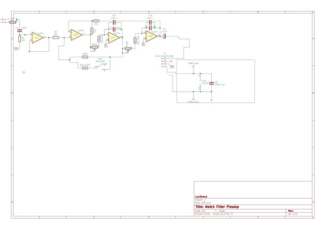
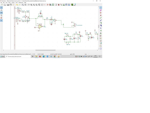
I have been using this opamp as well as opa2171 and opa4171 as it was advised by a member of your team. I wanted to ask for advice on what resistor values to use to create a voltage reference point when using these opamps? My design uses a single battery power supply and whenever using the inverting opamp as an input for the signal, the non inverting is connected to a Voltage reference point that I create using two 47k resistors, one to the rail and one to ground. Should I consider using other values(smaller/bigger?), and if so, why?

Regards,

Danilo

  • Hi Danilo,

    The newer versions of the OPAx171 devices are the OPA2991 and OPA4991.

    If it is a battery powered application increasing the values of the resistors would help save power. But if you provide any filtering with a capacitor in parallel with the resistor to ground then increasing the resistor values will increase the start up time due to the RC charging. However, this may not be an issue in your design. 

    Increasing the resistors will also introduce more noise into the circuit which will be amplified by the noise gain (Rf/Rg + 1) of the amplifier. The noise can be reduced by adding a capacitor in parallel to the resistor to ground.

    Decreasing the resistors will increase power consumption which is typically not desired in battery operated. 

    Lastly, if you create a bias voltage of mid-supply with two equal value resistors, the output will not be biased to mid-supply unless the input is AC coupled. You will need to consider that the bias voltage gets amplified by the noise gain of the amplifier to the output. For example, if you have an inverting signal gain of -1V/V and you want to bias the output up to mid-supply the bias voltage will need to be equal to Vcc/4. The bias voltage will see a gain of 2V/V to create an output voltage of Vcc/2.

    Thank you,

    Tim Claycomb

  • Hi Danilo,

    a schematic would be helpful Relaxed

    Kai

  • Hi Tim, 

    Thank you for your explanation. Here is the feedback of our customer,

    Yes, the startup time is not a problem. 

    The circuit is a state variable filter audio preamp, I use 47k resistors for Vref and a 10uf capacitor to filter it out. 
    So, I understand the advantages and disadvantages of using a bigger resistor, which seems to be very favourable to what I am looking for as I can always increase the value of the filtering cap. 
    What I don't understand is what are the advantages of using 2 smaller value resistors (10k for example)? Is noise reduction the only advantage,or is there anything else that the circuit would benefit from? Would it increase headroom/ decrease rail clipping?
    At the end of the day I would rather reduce the power consumption if using smaller resistors do not bring any benefits rather than reduced noise.
    Hi Kai,
    Here is the schematic diagram from our customer.
    Regards,
    Danilo
  • Hi Danilo,

    The main benefit of using smaller resistor values is reduction of noise and reduction of errors due to input bias currents. However, CMOS amplifiers like the OPA2171 or OPA2991 have pA of Ib so it takes a very high value resistance to create a substantial error.

    There also might be cost benefit for lower value resistors if the customer can use resistor values that are already used throughout the design. Typically, purchasing higher volumes leads to lower costs.

    Using higher/lower value resistors for the voltage divider on the non-inverting input will not change the common mode voltage range or output voltage swing of the device.

    Lastly, one consideration would be the input impedance of the amplifier if you decide to use very high value resistors. But this would require extremely high resistor values and use an op amp with a low input impedance. For example, if you use 10Mohm resistors and the amplifier only has 100Mohm input impedance, you'll likely see an error in the voltage divider voltage. If you use any modern amplifier, this would not be an issue. Most modern CMOS amplifiers are going to have GΩ or TΩ of input impedance (the OPA2990 has 6TΩ of common mode input impedance).

    Thank you,

    Tim Claycomb

  • Hi Tim,

    We have received this feedback form our customer,

    I noticed that increasing both the resistors to 180k do help reduce the current draw. Still, even like this the opamps are taking more current than the specs, unless the specs show the minimum.

    Regards,

    Danilo

  • Hi Danilo,

    The quiescent current specification shows a maximum of 595uA per channel at room temp. If the customer is seeing above 595uA/ch (1.19mA for a dual) something is wrong. However, this specification is for an output current of 0A so if the amplifier outputs a current into a load, that output current will add to the current consumption of the device.

    Thank you,

    Tim Claycomb

  • I noticed that increasing both the resistors to 180k do help reduce the current draw. Still, even like this the opamps are taking more current than the specs, unless the specs show the minimum.

    And what OPAmp supply current is the customer measuring?

    Kai

  • Hi Tim and Kai,

    Here's the response of our customer,

    I have used this summing circuit to do the test. It is another part of the circuits I'm making and uses a single opa171. With 180k resistors the current draw is 0.488 mA. With 47k reistor the current draw is 0.549. It's not a lot, but it does change the current draw. I'm trying to find a reason to why I shouldn't use the bigger resistors?

    to me, it is extremely important to reduce the power consumption and if I can do that by using that 180k value range and keep the noise figures at an acceptable level, I would definetly go that route unless it is not advised by TI.

    Regards,

    Danilo

  • Hi Danilo,

    if the low supply current is what counts, I would go with the 180k resistors. I don't see any issue, provided this 10µF low pass filtering cap is mounted across the lower 180k resistor.

    Kai

  • Hi Tim and Kai,

    Thank you very much for your feedbacks and suggestions. We really appreciate your help.

    Regards,

    Danilo