This thread has been locked.

If you have a related question, please click the "Ask a related question" button in the top right corner. The newly created question will be automatically linked to this question.

LM2917-N: Hall effect (TMAG5111) to Frequency to Voltage converter (LM2917) output circuit to determine acceleration

Part Number: LM2917-N
Other Parts Discussed in Thread: TMAG5111, OPA191

Hi,

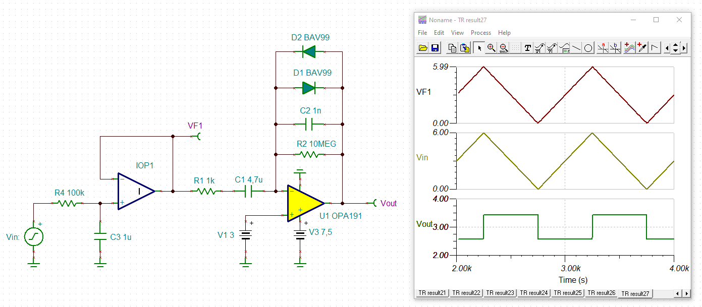
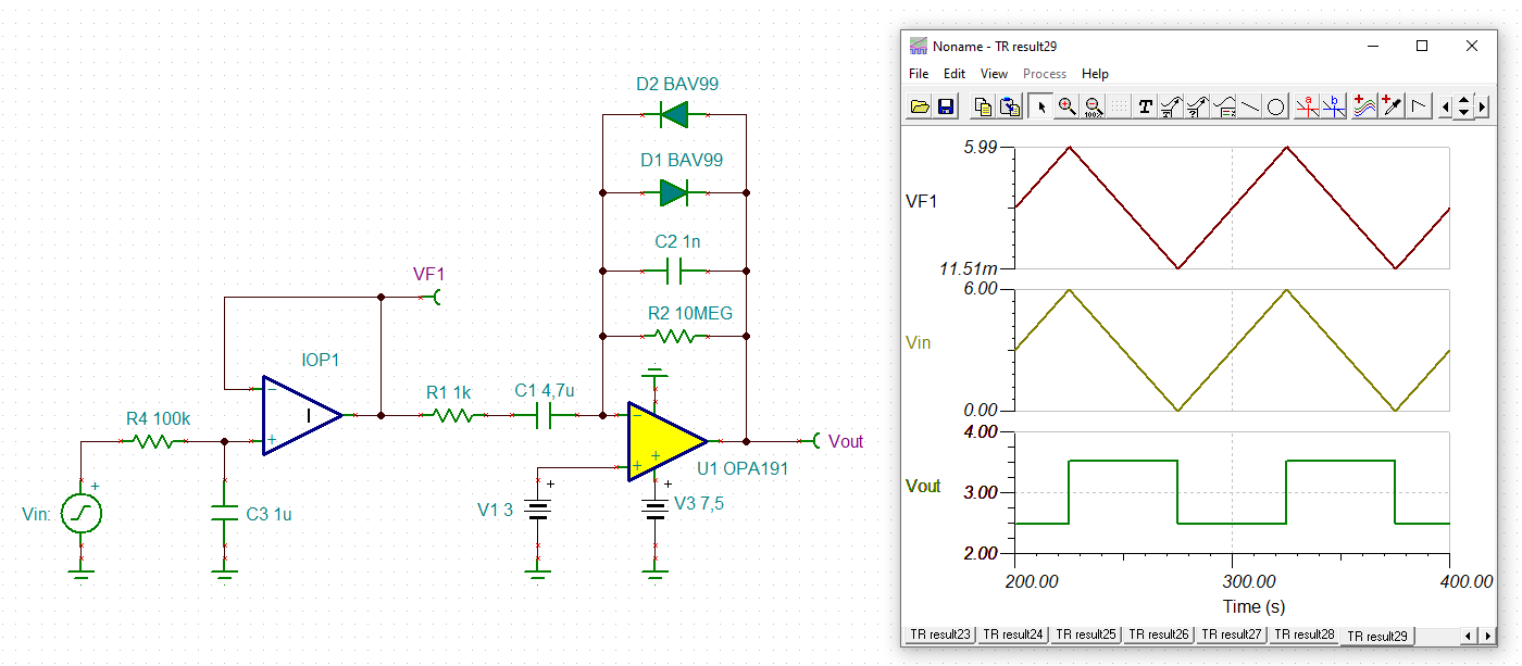
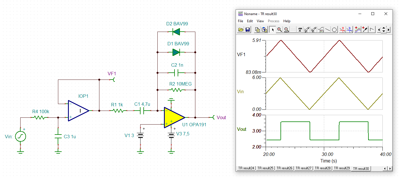
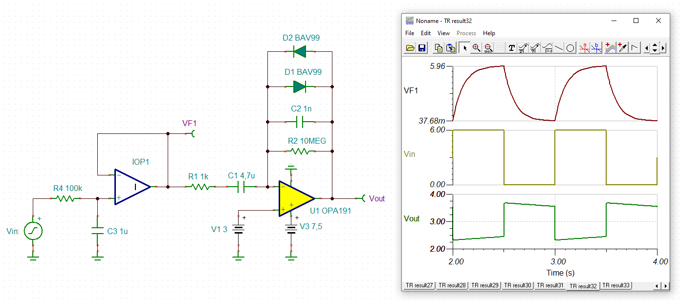
Any design suggestions to determine the acceleration out of the LM2917? Basically a tachometer, a hall affect sensor (TMAG5111) input to the LM2917,  input frequency range from 0 to 400 Hz. The DC output from the LM2917 is where I want to determine acceleration, I was thinking about a differentiator op amp circuit design to a comparator to determine positive acceleration or negative acceleration. I don't need a value for the acceleration just need to determine if the speed is changing, and in what direction, going faster or slower.   

  • Hello Brandon,

    I don't have any direct experience applying the LM2917N to obtain acceleration, but it would seem that it could be part of an overall system designed to accomplish that task.

    Likely, you are aware that acceleration is the first derivative of velocity; a = dv/dt. The LM2917N can be applied as a frequency to voltage converter (F-to-V) which provides a direct conversion of speed (velocity) to an output voltage. Then, its output could be applied to a differentiator circuit to obtain an indication of acceleration. Its output voltage would be a function of the the Hall Effect sensor's acceleration. 

    There is a TI Analog Engineer's Circuit for an op amp differentiator. It provides the information needed to design a differentiator based on the application requirements. You can find it here:

    https://www.ti.com/lit/an/sboa276c/sboa276c.pdf

    Alternately, TI has a Hall Effect sensors within the Sensing Product product line. I am not familiar with them, but possibly there is something that will accomplish the requirement more directly.

    Regards, Thomas

    Precision Amplifiers Applications Engineering

  • Thanks Thomas,

    I've been using this circuit design reference, and simulating it, there seems to be a lot of pitfalls, challenges when trying to design the circuit in order to pick up the low differentials (change in voltage / change in time) vs picking up the high differentials. Was thinking about other designs phase frequency detector, maybe charging up different capacitators and comparing their voltages, not sure. 

  • Hi Brandon,

    I would do it this way:

    brandon_lm2917.TSC

    Important is an OPAmp with a low input bias current and a low input offset voltage. The OPA191 is therefore a good choice for the differentiator OPAmp. And don't forget the diodes in the feedback path. They prevent the OPAmp from going into saturation.

    The first stage merely simulates the finite rise time of LM2917.

    Kai

  • To not overload the output of LM2917, R1 should better be increased from 1k to 10k.

    Kai

  • Thanks! Kai

    I was just going through your simulation, looking good, going through some quicker accelerations, no issues so far. Thank you!

    -Brandon