This thread has been locked.

If you have a related question, please click the "Ask a related question" button in the top right corner. The newly created question will be automatically linked to this question.

TLV314: Offset voltage in MFB configuration

Part Number: TLV314
Other Parts Discussed in Thread: TINA-TI

Hi, 

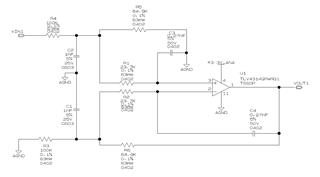
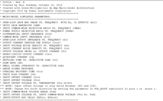
I have one MFB circuit built using TLV314.

I am assuming that spice model of TLV314 doesn't include offset voltage.

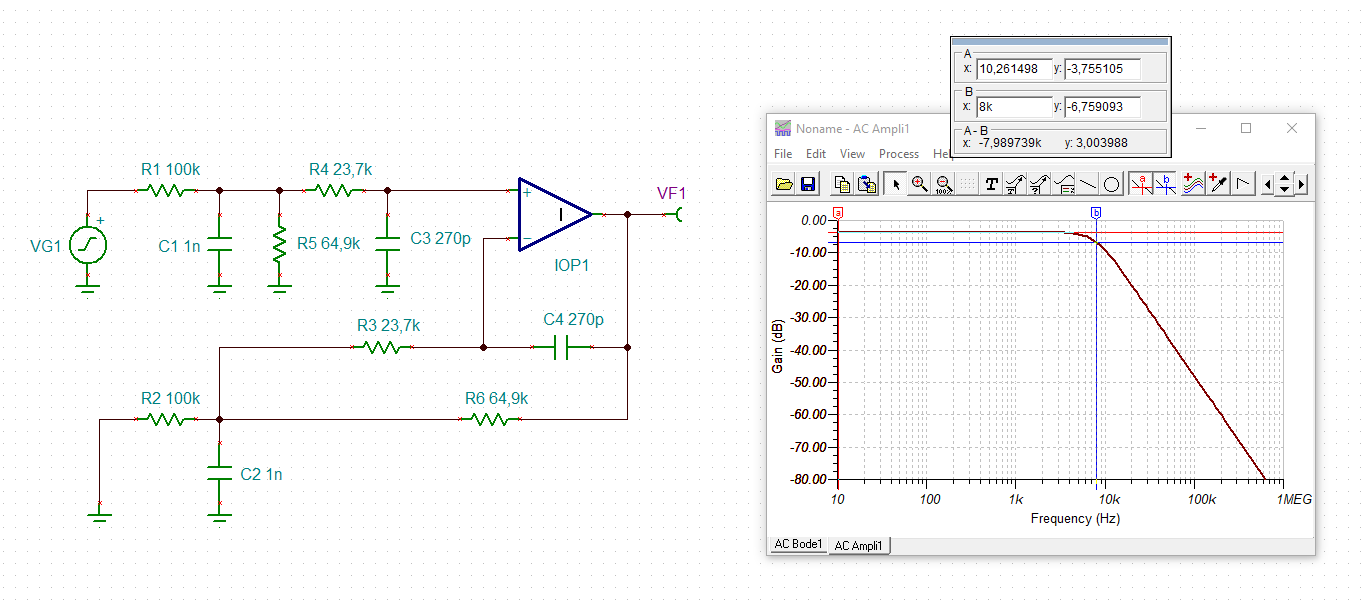
In case of steady state, input will be attenuated by Rf/Rin which is ~0.649.

Vout = 0.649*Vin

To consider offset also in calculations, should I directly add the Voffset + Drift over temp to the final output 

Vout = 0.649*Vin + Voffset.total

OR

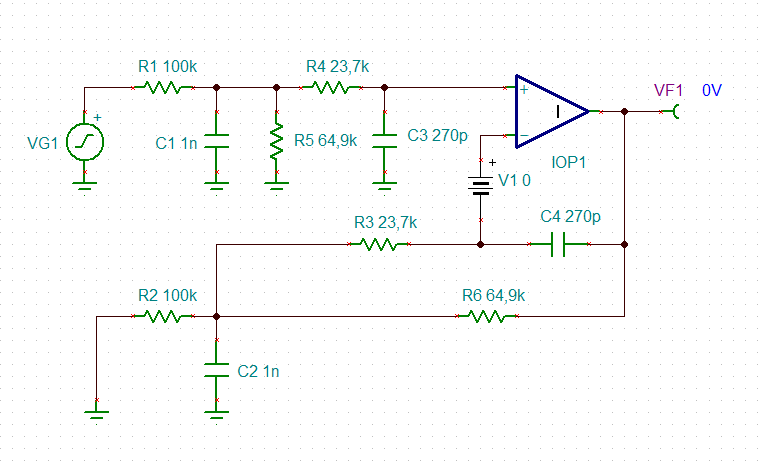
Since generally it is considered that the offset votlage source is on the non inverting terminal, I should use that and non inverting gain which is (1+Rf/Rin) and Add to the output:

Vout = 0.649*Vin + Voffset.total * (1+Rf/Rin)

Which way should be correct approach?, please suggest if none of above is correct approach.

Thanks in Advance!

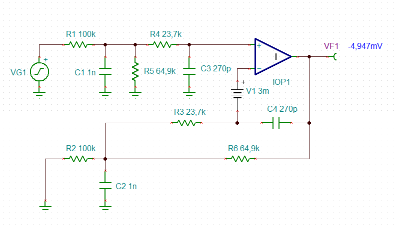
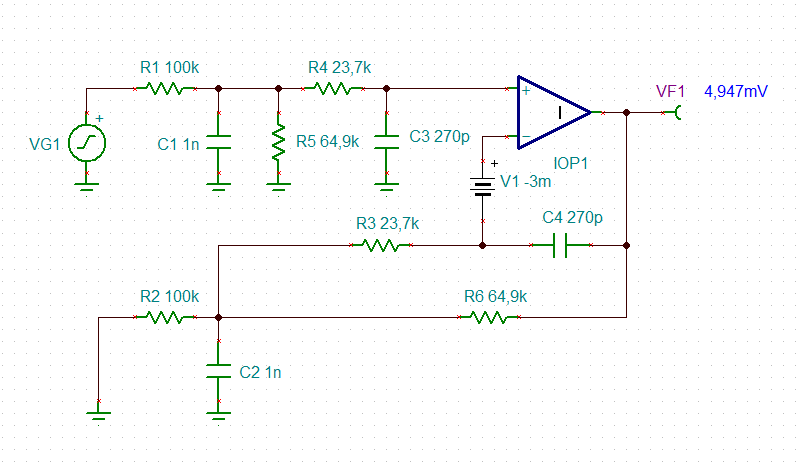
Please refer below circuit:

  • Hey Sunney, 

    Looks like you have adapted a diff to single audio differential filter design? The MFB filter is designed to work with an inverting input signal, so you can probably eliminate all that stuff on the non-inverting side and run inverting if that will be acceptable. Your actual filter shape running non-inverting (neglecting the filter on the non-inverting side) is the noise gain shape of the MFB, maybe not what you want as it always peaks lot more than the MFB inverting input shape. 

    Anyway, for your offset gain, use the DC noise gain - your 2nd choice. 

  • Hello Sunney, 

    Here is the netlist of the macro model, Vos is modeled. 


    All the best,
    Carolina

  • Hi Michael,

    Thank you for pointing that out. I was using MFB equations to understand the circuit and unfortunately the circuit simulation and math was matching. (may be I was doing something wrong).

    Since the input signal is not of differential nature, is it still ok to use this configuration?

    Your actual filter shape running non-inverting (neglecting the filter on the non-inverting side) is the noise gain shape of the MFB, maybe not what you want as it always peaks lot more than the MFB inverting input shape.

    Can you please explain above quoted little more.

    My understanding for the filter circuit from this is:

    1. It is not an MFB (even though it looks like)

    2. It is differential to single ended opamp circuit

    3. It is configured as non inverting op amp

    4. Is output of this configuration include noise gain? like o/p will be = (noise gain * Vin) => (1+Rf/Rin)*Vin?

    5. And if I use MFB configuration, (inverting input one) and neglect the non inverting as u have suggested, I might need one more inverter stage, correct?

    Thanks again for correcting my course.

    Regards,

    Sunney

  • Thank you Carolina

  • If you need non-inverting active filter, you can use a sallen key filter topology 

  • Hi Sunney,

    why not running a TINA-TI simulation?

    sunney_tlv314.TSC

    Kai

  • Incidentally, if I put the inverting side RC into the MFB tool, it will plot the noise gain - that is the gain this circuit produces from the V+ input to the output - so what is happening is the RC poles on that V+ input path are apparently cancelling the peaking the filter is producing. 

    So let's look at the output spot noise, using Kai's file with ideal op amp, only R noise sources and the frequency response. And there is that peaking around 8kHz, like the NG profile.