This thread has been locked.

If you have a related question, please click the "Ask a related question" button in the top right corner. The newly created question will be automatically linked to this question.

LMV331: Output during power on

Part Number: LMV331
Other Parts Discussed in Thread: LM393LV, TLV7041

Hi,

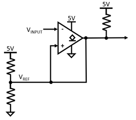
I'm considering using the LMV331 in the configuration depicted in the figure below. With this configuration, if VINPUT > VREF, the output will pull to GND and also pull the "+" input of the LMV331 to GND. As a result, the output of the LMV331 will become latched because if the "+" input is pulled to GND then VINPUT will always be greater.

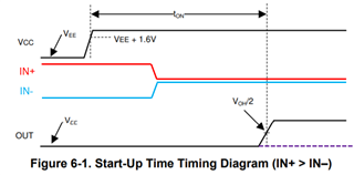
However, while the LMV331 is powering on and VREF is also being established, is it possible for the output to be pulled to GND because VINPUT < VREF because VREF is still coming up? Perhaps another way to ask this question is whether there is an interval after power on during which the output remains open regardless of the state of the inputs? Or will the output change as soon as VCC+ reaches the minimum value for operation.

Regards,

James

  • The LMV331 does not have a power-on reset circuit. The LM393LV or TLV7041 do, but only until VCC has reached the minimum.

    You can start VREF at a higher voltage by putting a capacitor in parallel with the upper resistor. (This implies that the comparator must charge the capacitor when latching, so you might need a series resistor to prevent large currents.)

    Alternatively, put an actual latch with a clear input behind the comparator.

  • Thank you Clemens!

  • Thanks for your post James and Clemens for your excellent support.

    TLV7041 is probably the best option because of the POR circuit that causes the device to start with high Z output and because the device has integrated hysteresis.  This would help keep the output latched, even if the input goes down to ground.

    Chuck

  • Hi Chuck,

    A quick and probably silly question about the TLV7041. When the ton period expires, does the output reflect the input pin states at that instant *or* does it reflect the input pin states when VCC crossed the VEE + 1.6V threshold? I believe it's the former case and not the latter in which case the dotted purple line reflects the output when the ton period expires.

    Regards,
    James

  • After ton has expired, the device works. This implies that the propagation delay time is 3 µs, not 200 µs.

  • Hi James,

    a very basic question must be asked: How shall a safety circuit behave during a singular event like the power-up period or power-down period? And how shall it behave during a longer lasting power-down? I think a battery backed-up power supply should be used to guarantee an interruption-free operation.

    Additionally, I would use a proper reset controller to handle brown-out conditions and generate a dependable power-on reset. I have made very good experience with the MAX1232 which I use in a microcontroller circuit which must work ultra reliable. TI's TL77xx series is also working very trustworthy.

    Kai

  • Thanks Kai and Clemens for your continued support.

    James,

    thanks for posting your question and let us know if you have any additional questions.

    Chuck