This thread has been locked.

If you have a related question, please click the "Ask a related question" button in the top right corner. The newly created question will be automatically linked to this question.

THS4021: Technical issues

Part Number: THS4021

Hi team,

I got a question from customer.

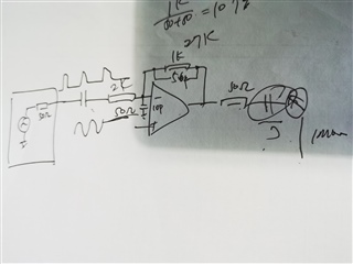
Using the THS4021 op amp chip, no matter how it is connected, it will self oscillate.

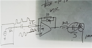
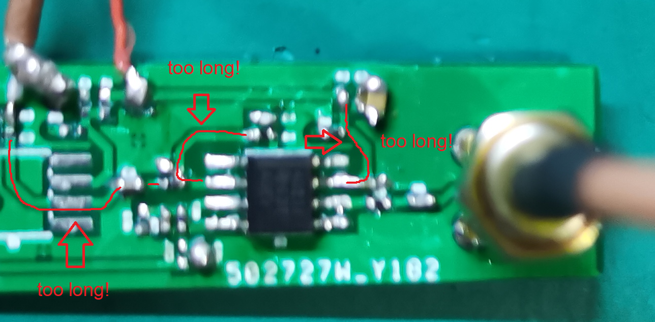
The circuit board is as follows:

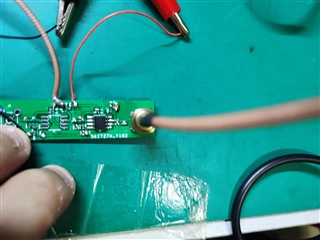
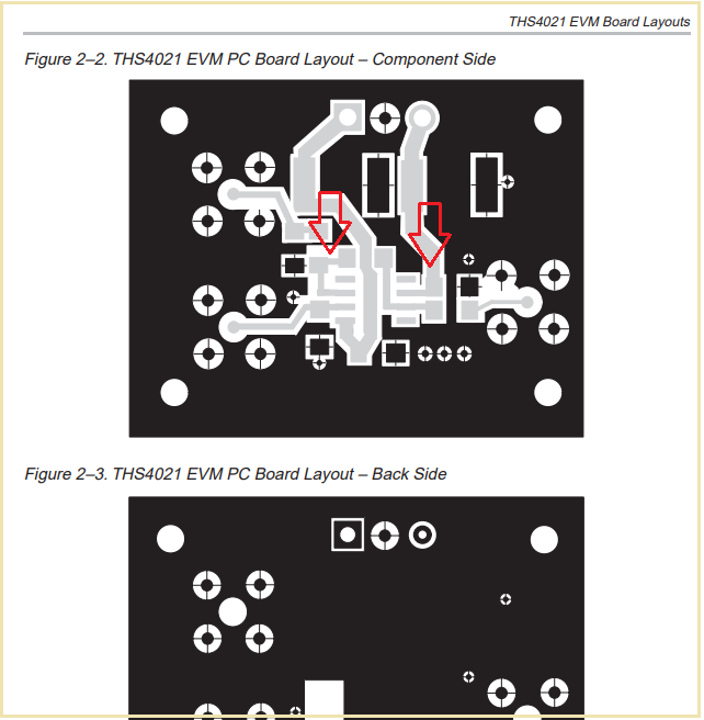
No matter whether the single power supply or dual power supply are all oscillating, and then digs the ground behind the chip according to the evaluation board, it is also unable to improve.

The only difference between this circuit and the circuit is the porcelain capacitor and 0.1uF used by 10uF.

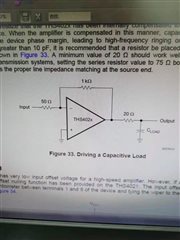
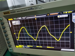
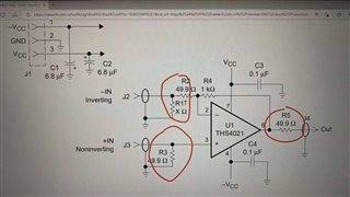
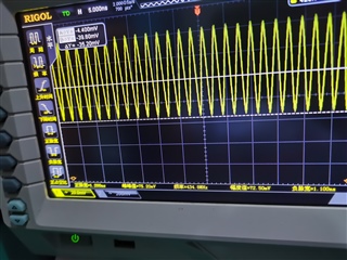
The circuit is mainly connected according to these two circuits. If there is no input signal at the inverting end, there will be oscillation output. After adding the input signal, it cannot be amplified, and there is also severe oscillation on the waveform

Add some information,After adding the inverted input signal, such oscillations are superimposed on the output pulse.


Thank you very much for your help.

Best regards,

  • Morning Xonghui, 

    The THS4021 is a decompensated VFA which will require a relatively high noise gain at loop gain =0dB crossover for stability. Looking at this last schematic, hard to tell what is going on, 

    1. You should use a 50ohm input scope, not 1M - these parts prefer 100ohm load and the signal path will be cleaner

    2. V+ node should be grounded, preferably through a 20ohm R close to the pin to deQ self resonance in the input transistor. 

    3. Feedback? I see 1k and 27k? In any case, I also see a feedback cap and cap to ground - I call that the inverting comp approach. The ratio of the cap to ground on the inverting node over the feedback cap should exceed the min gain stable target - use perhaps 12V/V here. 

    This inverting comp idea is considered as the 1st example in this article, 

    https://www.planetanalog.com/applying-high-speed-de-compensated-vfas-hitting-performance-targets-while-tuning-phase-margin-insight-10/

  • Hello Zhonghui, 

      Following on Michael's third point, is the customer using this schematic

       Or this one?


      Also, are they driving a capacitive load, if so, how much? 

    Thank you,
    Sima

  • Hi Zhonghui,

    your layout is not optimal. The board is too narrow so that the decoupling cap cannot profit from a ground plane. Also, the decoupling cap is too far away from the OPAmp and the signal traces at the -input are too long:

    See how the EVM is doing it:

    Keep in mind that with such HF OPAmps every single millimeter counts. A couple of millimeters can make the difference between success and failure. Your layout cannot work!

    Also, if you feed the supply voltage to the board via a wire (and not having the copper trace running over a solid ground plane!), I would heavily recommend to use a Pi-filter instead of a simple decoupling cap. Or add at least a 10...22R resistor or a ferrite bead which you mount close to the supply voltage decoupling cap.

    Kai