This thread has been locked.

If you have a related question, please click the "Ask a related question" button in the top right corner. The newly created question will be automatically linked to this question.

TLV9062: TLV9062S pspice model ERROR(ORPSIM-15141):

Part Number: TLV9062
Other Parts Discussed in Thread: PSPICE-FOR-TI, TINA-TI,

Hi Team,

A customer found a issue on TLV9062S Pspice model.

Question as below.

 In a design that I am doing I am considering using the TLV9062S op-amp.

To validate the performance of the TLV9062S in the application, I would like to initially do a PSpice simulation.

To make it simple, today I downloaded and started the PSpice-for-TI tool, and built a simple circuit that just biases up the TLV9062S PSpice model, loaded from the TI op-amp library within the PSpice -for-TI tool. I did this to validate the PSpice model for the TLV9062S that I got from TI.

The simulation fails with the message "ERROR(ORPSIM-15141): Less than 2 connections at node X_U1.XU2.N4."

This is an internal node within the TI simulation model that is not connected to anything,

and the simulator generates an error, it does not allow floating nodes. Since this is inside the model, I cannot fix it with any confidence. The PSpice model that I am using is "TLV9062S - Rev. DCreated by Paul Goedeke; July 27, 2018"

Thank you for your clarification.

Regards,

  • Hi Frank,

    can you show a schematic of your biasing circuit?

    If there's trouble with PSpice, I would run the simulation in TINA-TI.

    Kai

  • Hey Frank, 

    Do you see this same issue with TLV9062 model? 

    All the best,
    Carolina

  • Hi Kai,

     I can't actually post the biasing circuit, as noted above, but it's 3.6V to VCC and SHUTDOWN*, a 10k feedback resistor from output to (-) input, and a 10k resistor to a 1.8V supply from teh (-) input, with the (+) input tied directly to the 1.8V supply, and the model's VEE is tied to GND0. The simplest possible biasing circuit.

    Thanks.

  • Hi Caro,

    Yes, I have confirmed. The TVL9062 model simulates without error, it is only the TLV9062S that fails.

    Thanks.

  • Hey Frank, 

    Please use the TLV9062 model as we work to fix the shutdown version. 

    All the best,
    Carolina

  • Hi Caro,

    Thank you.

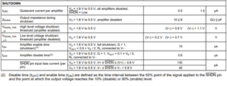
    The reason that I am doing this simulation is to try to understand what the dependencies are on the enable/disable time for shutdown,

    which a feature unique to the TLV9062S model, so it's only the TLV9062S model that can be used.

    If someone knows what the conditions are for which worst-case-slow enable-time occurs,

    and what the worst-case is for 3.6V from 0 to 85C temperature, then I'd be done with the inquiry.

    The TLV9062S is uniquely well-suited for the product that I am designing, but it has a 10us typical enable-time,

    and I need to know what the worst-case is: I have a 22us-long signal that I need to capture the end of,

    so I need to know worst-case delay for settling after enable.

    Thanks.

  • Hey Frank, 

    The model does not cover enable/disable time for shutdown. It only covers enable/disable based on the voltage applied to the shutdown pin, all other functionality is identical to the TLV9062 model. Also please keep in mind that the models are based at room temperature (25C). Montecarlo will not work on the model as that is not built in. 

    As for the shutdown timing, I suggest consulting the datasheet: 

    And section 9.3.5 of the TLV9062 datasheet: 

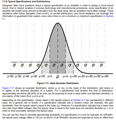
    These general purpose amplifiers have specified typical characteristics but very rarely max/min specifications. Therefore, statistics may be leveraged as seen in section 7.3.9 of the OPAx991 datasheet: 

    Since the enable/disable time is has a mean that is usually a nonzero value, the typical value is equal to the mean (µ). "For specifications with no value in the minimum or maximum column, consider selecting a sigma value of sufficient guardband for your application, and design worst-case conditions using this value. For example, the 6-σ value corresponds to about 1 in 500 million units, which is an extremely unlikely chance, and could be an option as a wide guardband to design a system around. " 

    Please keep in mind that this data is from a specific sample of devices at a specific point in time, and there may be additional factors, like process shift, that affect the mean and standard deviation.

    All in all, the safest route is for the customer to test in lab, in the specific care-about conditions. 

    All the best,
    Carolina

  • Hi Carolina,

    thanks for trying. If the model does not include enable timing,

    there's no need to worry about using simulation to test the design;

    the design has to be bench-tested, and over temperature and voltage, and with margin allowed for make-tolerance.

    customer hopes that some day the models will incorporate those effects, and save lots of design-time.

    Thanks.