- Ask a related questionWhat is a related question?A related question is a question created from another question. When the related question is created, it will be automatically linked to the original question.
This thread has been locked.
If you have a related question, please click the "Ask a related question" button in the top right corner. The newly created question will be automatically linked to this question.
Hi,
We are using TLV9002IDR and LMV358AIDR in our projects. Working Fine. But if we connect 4-20mA Sensor (24V supply, 2-wired sensor) when board is ON, the board/MCU will get restart. After restart will work fine.
We need to avoid this due to data loss in this time, if the customer wants to replace the sensor without loosing the data.
Kindly, PFA the schematic, what will be the issue for the restart?
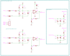
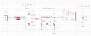
But in another Project Board, we are using MCP6021T-E/OT Amplifier, That board is not restarting even the Circuit is same.
Thanks and regards,
Naveen K
Hey Naveen,
Just to confirm, you are seeing this issue with both TLV9002 and LMV358 as U16 in the schematic? Or is TLV9002 used somewhere else? Is everything else the same on the board where MCP6021 is working? I don't suspect the issue is with the amplifier if the MCU is restarting, as the amplifier is providing an analog input to an ADC, and is not in the power tree for the MCU.
Best,
Jerry
Hi Jerry,
Thank you for the information.
1. Yes, issue with both TLV9002 and LMV358 as U16. For the same project we are using TLV9002 for few boards and LMV358 for few boards for Testing due to cost difference.
2. Yes, Same schematic is using for MCP6021, it's a single channel. Board is not restarting. That is why we are struck to find the issue.
3. We need to know, where is the Problem. Kindly advise.
Thanks and regards,
Naveen k
Hey Naveen,
Could you please provide oscilloscope captures of pins 3, 1 and 8 of the DUT when plugging in the probe and observing the reset? Also, can you provide the power rail information? How much current can your 3.3V rail source (also, is the power architecture the same across both boards)?
Best,
Jerry
Hi Jerry,
Thank you for the information.
Unable to access the Oscilloscope due to some issue. I will try to provide after some time.
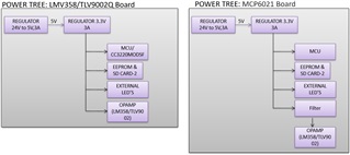
PFA the Power Tree. Power tree will be same for both the boards. But, only the difference is,
In MCP6021 board, MCU is directly connected to 3.3V source. But Amplifier MCP6021 is connected through Filter, PFA the Filter Schematic.
In TLV9002/ LMV358 board, both MCU and TLV9002/ LMV358 is directly connected to 3.3V source(You can see in previous Schematic).

In TLV9002/ LMV358 board, If we connect 3.3V source directly to the Amplifier input while board is power ON, it will not restarting. It will restart, if we connect 24V (4-20mA) Sensor.
In MCP6021 board, It will not restart for both the cases.
We struck to find the problem source, Kindly advise.
Thanks and regards,
Naveen K
Have you tried connecting the LMV358/TLV9002 on the other side of the filter? That's a significant amount of capacitance and could help mitigate the instantaneous current draw of connecting the sensor. However, it would be strange to me if a 3A regulator couldn't take an 80mA current pulse.
Best,
Jerry
Hey Naveen,
Has this issue been resolved? I am marking my above answer as TI thinks resolved, but feel free to respond to the thread if the issue is not resolved and needs further troubleshooting.
Best,
Jerry
Hey Naveen,
It may be conducting through the ESD diodes of the device, which may be damaging them. MCP6021 does not have ESD diodes to Vcc, only to Vee. TLV9002 and LMV358 both have ESD diodes to Vcc. This could explain why the 1k series resistor prevents the issue. (see below screenshots)
MCP6021: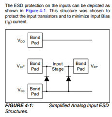
LMV358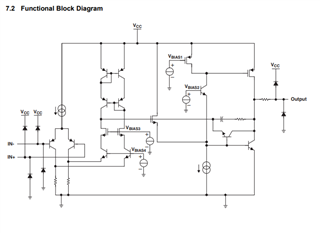
TLV9002
Best,
Jerry
Hi Jerry,
Thank you for the information.
1. I removed the LM358/TLV9002 IC in board, remaining components kept as it is, Still board will restart when we connect the Sensor. So i got to conclude that Restart issue with External ESD Diode D10 and D13 only. LM358/TLV9002 and it's internal ESD Diode not causing the restart issue. My conclusion is correct?
2. I removed the external ESD Diode on LM358/TLV9002 board for testing, LM358/TLV9002 IC got damaged after connecting the sensor. So, we can't remove the Diodes also.
3. We have External ESD Protection Diodes(BAT54) on both LM358/TLV9002 and MCP6021 board as given the schematic earlier, Why in MCP6021 board external Diode not giving the path to restart? It is confusing us to conclude the issue source. Any method to identify here?
Kindly advise, how we can solve this Restart Issue?
Thanks and regards,
Naveen K
Naveen,
It looks like it is confirmed that the connecting the 24V to the 3.3V is causing the restart. Is everything completely the same with the MCP6021 board? It makes sense that removing the external ESD diode will cause damage to the part, but it doesn't make sense that an identical schematic will not see the same issues if the issue occurs even without the part populated.
As for how to fix the restart issue, does the below comment not work? Otherwise I would suggest a voltage divider to not attach 24V input suddenly.
If I connect 1K series resistor to the sensor output, board won't restart even if we connect the sensor when board is ON
Best,
Jerry
Hi Jerry,
Thank you for the information.
1. LM358/TLV9002 board and MCP6021 board circuit will be same except Filter, MCP6021 VDD and Diode cathode is connected to 3.3V through Filter circuit attached earlier (and MCP6021 Board size will be 3.2times bigger than LM358/TLV9002 board). But i have removed the Filter component and directly connected to 3.3V, it is not restarting. Don't know the reason.
2. If i connect 1K series resistor, it will act as Voltage divider with help of 150Ohm on board resistor (R49, R51). Is there any other better solution than this? Kindly advise.
3. We have chosen 150Ohm resistor to give maximum 3V for amplifier input, if the 4-20mA sensor output is 20mA. If we add 1K series resistor voltage will not get divide and we will get same voltage as without series resistor, right?
Thanks and regards,
Naveen k
Hey Naveen,
For a current sense circuit, is the output a constant current or a constant voltage, if it's a constant current then adding a series resistor to drop the voltage won't affect the voltage across the sense resistor, as the current in the loop will be the same, thus generating the same voltage across the sense resistor.
For an apples to apples comparison, would you be able to put a TLV9001 on the MCP6021 board so we can truly compare 1:1? Since this happens even with the amp not populated I suspect the issue is not the amp.
Best,
Jerry
Hi Jerry,
Thank you for the information.
Yes we can replace TLV9001 on the MCP6021 and MCP6022 on TLV9002, We will procure and try.
Yes, true. Issue not with Amp. But still not found, How, MCP6021 board not restarting?
Voltage Divider will be the right solution or any other method will be better?
Thanks and regards,
Naveen k
Hey Naveen,
As stated above, if the current is constant, (eg, does not change with the addition of the 1k resistor) then the circuit should still function properly with the added 1k resistor.
If the issue is not with the op amp, this is out of the scope of the support I can give. This seems to be a system-level issue. The primary purpose of this forum is to support issues with the TI products, in this case, the op amp. I am assuming that the boards are not exactly 1:1, and in the discrepancies, you will find your issue.
Best,
Jerry
Hi Jerry,
Thank you for the information.
Issue related to TI Product only. If we not use ESD diode, restart issue will not happens, but Op amp will get damage. ESD diode will causing the issue and Diode is used for Protecting the Op amp. Then issue is with indirectly Op amp only, right.
Can we eliminate ESD diode to solve Restart issue? How we can protect the Op amp?
I have already shared the schematic for both the boards, both are same 1:1.
Thanks and regards,
Naveen K
Hey Naveen,
Forgive me if I have misunderstood, but the assumption that the amplifier is not the source of the issue was from the below statement.
I removed the LM358/TLV9002 IC in board, remaining components kept as it is, Still board will restart when we connect the Sensor. So i got to conclude that Restart issue with External ESD Diode D10 and D13 only. LM358/TLV9002 and it's internal ESD Diode not causing the restart issue. My conclusion is correct?
That being said, have you measured the current through the sensor when adding the 1k series resistor?
Also, have you been able to populate a TLV9001 on the MCP board to confirm?
Best,
Jerry
Hi Jerry,
Thank you for the information.
As we said, Board having CC3220MODSF and LM358/TLV9002. We need to protect both from external interfaces like 4-20mA looped Sensors here.
Current is around 6mA, because Temperature sensor maximum output will be 20mA.
Yes we can populate, we are trying to procure, but due to NO-Stock globally, we are awaiting for Stock resume. As per our not-populated trial OPAMP not causing issue, Diode giving the path. Kindly re-verify our schematic and suggest the Protecting circuit for this issue.
As i mentioned, Once sensor was connected and board has restarted, Then both will work perfectly with out any issue until we unplug the sensor and insert it back again.
Thanks and regards,
Naveen k
Naveen,
Test the full range of the temp sensor. If the full range of current is unaffected after adding the 1k resistor, you do not need to change anything else in the design. If the range of currents is reduced, you may add gain to your circuit to capture a similar granularity to the previous circuit.
Best,
Jerry