This thread has been locked.
If you have a related question, please click the "Ask a related question" button in the top right corner. The newly created question will be automatically linked to this question.
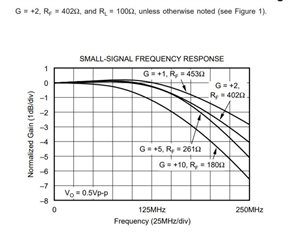
1. The datasheet of OPA691 mentions the optimum value of feedback resistance that ensure reasonably good stability and bandwidth.
The specs mentioned are for ± 5V rail. Will it hold good for ± 3.3V?
If not, what way the optimum value of feedback resistance change?
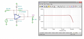
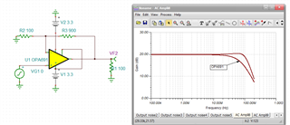
2. What would be the bandwidth for gain of 10 and if feedback resistor is 1KΩ for ± 3.3V.
The BW vs gain and Rf is reasonably constant with supply voltage, 1kohm sounds high for gain of 10 - you could try to simulate that in TINA.
If you need better BW vs Gain the OPA684 does a better job at higher gains if its about 120Mhz is good enough.
Hello Shobha,
1) As Michael said, BW vs gain/RF are constant with supply voltage. So, the specs should remain constant for various power supply/rail configurations.
2) Small signal frequency response for different gain settings with recommended feedback values:
The simulation models for the OPA691 are located here.
Thank you,
Sima
I had some previous sim files already set up, here is the OPA684 at gain of 10, Rf=900ohms - the models generally do not try to include much in the way of supply variation on AC results, I put it to +/-3.3V supplies for this app, but +/-5V would look the same

And then dropping in the OPA691 to this same schematic, this is due to the higher inverting input R for the OPA691. The OPA684 was a unique CFA in that the buffer across the inputs was closed loop to reduce the open loop impedance looking back into the inverting input - this really helps the higher gain BW hold up better than more classical CFA designs like the OPA691.

TINA file with the OPA684,