This thread has been locked.

If you have a related question, please click the "Ask a related question" button in the top right corner. The newly created question will be automatically linked to this question.

INA236: Questions on design with INA236 and INA231

Part Number: INA236
Other Parts Discussed in Thread: INA231, INA228, INA229

team,

The customer raised some questions for application of INA231 and INA236. Would you please check and reply. Thanks

  1. For INA236 the Vsense is probed at the V- pin, for INA231, Vsense have a dedicate BUS pin, is it flexible to connect BUS pin to V-, V+ or other voltage point not connected to INA231?
  2. For INA236, the minimum current we could sense in light load is 5uV/Rsense? It could sense the current load which periodically change from 0~10uV/Rsense but with large error percentage?
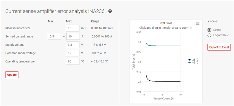
  3. From the diagram below, is this mean that the current error could be 40uV/Rsense when the conversion time is set to 140us?
  • Hello Max,

    Here are my responses to your questions:

    1. Yes, you can connect the VBUS pin to any voltage that is within the VBUS measurement range.  However, if you connect this to some pin other than V- or V+, then the power register will have the wrong value, which is fine if you are not using the power register. (Connect to V- to only have load power, connect to V+ to measure load plus power dissipated over the shunt.)
    2. The smallest LSB size for the INA236 is actually 0.625µV (with ADCRANGE = 1), however the ability to achieve this resolution depends on the device settings.  For this you will want to look at Table 8-2: INA236 Noise Performance, so that you can see the effective number of bits (ENOB) you get for the specified device settings. Note that this is for resolution, and there could be other error sources causing an offset. (but the device itself only has a 5µV maximum offset).  5µV is too much, you could potentially calibrate out that offset.
    3. This diagram shows the noise floor, so for example with 140µs conversion time you have your result ±20µV in measurement resolution. The device does have a 5µV offset maximum error, and a 0.1% gain error as well to consider. 

    I recommend looking at our TI Precision Labs video series which has a section on possible error sources and how to combine them for an expected maximum error: https://training.ti.com/ti-precision-labs-current-sense-amplifiers, (Section 3).

    Also, there is a calculator tool on the product page (https://www.ti.com/product/INA236) that you can use to help you estimate error for your given situation.  It looks like this:

    If you come to find that the INA236 does not have enough precision for you, then you may want to look into the INA228/INA229, as these have a 20bit ADC.