This thread has been locked.
If you have a related question, please click the "Ask a related question" button in the top right corner. The newly created question will be automatically linked to this question.
I'm trying to use the OPA2197 as a Single Supply.
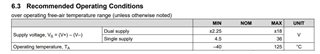
If you look at page 5 of the data sheet, it appears that it can be used as a single supply.
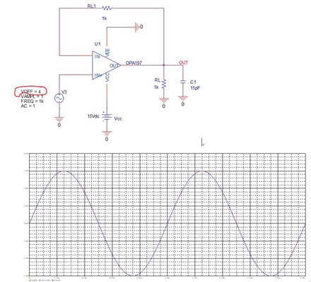
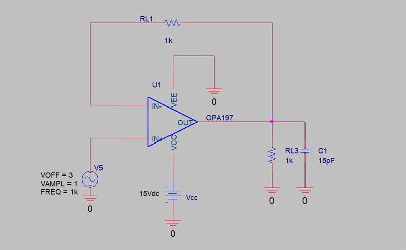
When I get PSpice model (sboma34b.zip) for OPA2197 from TI web and simulate it with a single supply structure, it does not work.
Simulation with dual supply structure works well.
In the simulation method, the negative power side of the sboma34b.zip file was treated as GND or -0.01V.
Please review the OPA2197 PSpice model for single supply.
Hi Lee,
I used the OPA197 simulation model available within PSpice for TI and set up a simple, single-supply test circuit. A single +15 V supply is applied to the OPA197 Vcc pin and the Vee pin is connected to ground. The OPA197 non-inverting input needs to be offset from ground so that the input common-mode voltage (Vcm) and output voltage (Vo) ranges are not violated. You can see the circuit below and the transient analysis result I received from the circuit with a 100 Hz sine wave input. The model behaved as expect with the single supply. The PSpice model on the OPA197 model on the web page and that within the PSpice library should be the same because they are from the same one source.
Regards, Thomas
Precision Amplifiers Applications Engineering
Thank you for your confirmation.
However, it is slightly different from the conditions I simulated.
The conditions I made are as shown in the figure below.
I will clarify the simulation setting conditions.
I have confirmed that if you do it under the conditions you set it will work.
But the condition I simulated is VOFF=3V,VAMPL=1,FREQ=1k .
If VOFF=3V is set, the simulation will not proceed.
please check.
I also change Voff=3, VAMPL=1 in your simulation circuit to simulate, the simulation does not proceed.
Please check by correcting only Voff=3 in the circuit diagram I attached.
Also check by changing Voff=3, VAMPL=1 in your circuit.
Hi Lee,
I did some investigation of the simulation results. The problem is not the simulation model. The reason that PSpice for the TI simulation appears to be failing with the circuit is that the OPA2197 circuit is oscillation and it is not coming to a steady state solution.
There two elements in the circuit that are degrading the phase margin causing the circuit to be unstable. The 15 pF capacitor directly connected to the output pin and ground will degrade the phase margin by a small amount, but not enough to cause the circuit to become unstable. The big issue is the 1 kilohm resistor in the feedback path of this unity-gain buffer circuit. This resistor in conjunction with the OPA2197 input capacitance adds enough phase shift in the loop to the point where the phase margin drops to zero and the feedback becomes positive resulting in oscillation.
If you take your circuit and replace the 1 kilohm feedback resistor with a wire you should find that the circuit readily converges and the buffer behaves as expected. I even tried leaving the 15 pF capacitor on the output in this condition and there wasn't any issue with stability.
Regards, Thomas
Precision Amplifiers Applications Engineering
Thanks for your analysis.
But I don't understand why the result is different when the offset voltage is 3V and when the offset voltage is 4V.
I want to know the stability of the single supply structure when the offset voltage is 3V and when the offset voltage is 4V.
When I do, AC simulation for stability in a single supply structure still does not produce results.
In the transient analysis, only offset voltage 3V did not come out, but for stability, AC simulation does not show both offset voltage 3V and offset voltage 4V.
If you share an example of stability analysis (Using Pspice) in buffer structure using OPA2197 in single supply structure, it will be very helpful for analysis.
The buffer circuit I am currently analyzing for stability is shown in the figure below.
Hi Lee,
TI has the Precision Labs - Op amps series in which one section is dedicated to stability analysis methods. It provides a very good treatment of the subject. TINA-TI Spice is used for the presentation, but that shouldn't matter. You should be able to set up the same analysis using PSpice for TI. You can find the stability sessions here:
https://training.ti.com/ti-precision-labs-op-amps-stability-introduction
I suspect the OPA2197 complex output impedance (Zo) may be changing in a manner affecting the phase margin with a shift in VOFFSET. Changing VOFFSET from 4 V to 3 V does change the output current and possibly Zo with it. The simulation models have their limitations because they can only go so far in simulating the actual silicon's electrical behaviors and may act differently under some conditions.
If you get the stability analysis set up for both VOFFSET at 3 V and 4 V you may find that the phase margin shifts from marginally stable, to unstable with only a small change in the phase margin. A small-signal transient analysis where overshoot or ringing is evident is a quick way to gauge the phase margin.
I will be gone on personal leave for the next week and a half and will not be able to assist any more until I return. Possibly one of my colleagues can assist you while I am gone if their time permits.
Regards, Thomas
Precision Amplifiers Applications Engineering
I ran stability simulation using the above buffer circuit.
However, in the single supply structure, stability results are not obtained in ac simulation for offset 3 V and offset 4 V.
In the dual supply structure, stability results in ac simulation are showing well.
I would like to conduct stability analysis in ac simulation for offset 3 V and offset 4 V in single supply structure.
I look forward to your help.
Hi HongGyo,
Could you try the latest PSpice model? The latest model is uploaded this morning, please see the link below.
https://www.ti.com/product/OPA2197-Q1#design-tools-simulation
Best,
Raymond
I got a new OPA2197 simulation model sboma34c.zip from the TI Wep site.
If you run PSpice after unzip, the simulation will shunt down.
Currently, my tool is version 17.2.
please check.
Hi HongGyo,
I was able to upload the model into my PSpice tool, see below. The model is tested with Cadence 17.4 version.. The current PSpice-For-TI can be downloaded from the link below. It should be very similar to V17.4.
https://www.ti.com/tool/PSPICE-FOR-TI
Best,
Raymond
I downloaded the PSpice model of opa2197 from the TI website and performed the simulation.
I talked about the symptom that the tool version 17.2 shuts down when you run the newly uploaded model.
Raymond reply said to use tool version 17.4.
I installed PSpice for TI 17.4 and run the PSpice model of opa2197.
However, the same shutdown symptoms occur.
Please download the PSpice model of opa2197 from the TI website and run it.
Hi HongGyo,
We are going to close this inquiry, since you have opened a new one of the same issues in the forum.
If you have additional questions, please let us know.
Best,
Raymond
Hi Raymond
The problem of single supply condition has not been solved yet.
Once the simulation model is solved, I will check the above again under the single supply condition.
There is currently an issue with using the new PSpice model from TI.
I hope the use of PSpice models is resolved.
If there are no problems with using the PSpice model, I will review the above again.
Hi HongGyo,
I have replied your inquiry in other thread, see the link below.
If you have additional questions, please let us know.
Best,
Raymond
Hi Raymond, Thomas
The above discussion was reviewed using the newly created opa2197 simulation model.
It was confirmed that both voff=3v and voff=4v in a single supply performed well in transient simulation.
Also, it was confirmed that ac simulation works well at voff=3v and voff=4v in single supply.
Thanks for the quick support.
Some of the things that were a little disappointing during this discussion are as follows.
1. If both single/dual simulation models are supported, I think that by creating an example file for each and uploading it to the TI web, the simulation model can be checked and users can use it easily.
2. There was a problem that an error occurred when running the example file downloaded from the TI web. I'd like to know why this problem occurs.
Thank you again for your much support.
Best Regards,