This thread has been locked.

If you have a related question, please click the "Ask a related question" button in the top right corner. The newly created question will be automatically linked to this question.

AMC1311: Temperature Error ~3% instead 0.29%

Part Number: AMC1311
Other Parts Discussed in Thread: TLV6001, TLV6002, AMC1301, AMC1100, AMC3330, AMC1350, AMC1300,

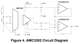
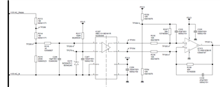
The following circuit seems to be highly temperature dependent:

0°C ==> 116,5V

22°C ==> 115,3V

60°C ==> 112,1V

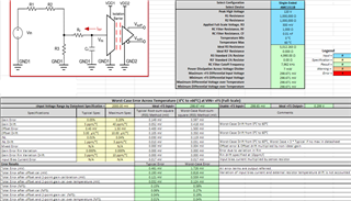
I used the AMC Voltage Sensing Calculator.xlsx and it gives me maximum 0.29% error over 0...60°C.

All resistors are 0.1%/25ppm/°C types. Any ideas?

Regards, Martin

  • Hi Martin,

    I assume that you are measuring the single-ended output voltage and back calculating to the input, can you please confirm? 

    The calculator only accounts for the error of the AMC1311B itself, not drift of the resistor divider or the error introduced by the differential to single-ended conversion. Are you able to measure the input and differential output voltage directly to confirm that the issue is with the AMC1311B?  

    Also, can you confirm the stability of the 3.3V source at TP304 over temperature? 

    I've configured the calculator as per your schematic and I see a maximum error of 0.58%, not 0.29%, can you please confirm any differences in our settings?

    I would recommend using the TLV6002 instead of the TLV6001 and buffering the resistor divider reference voltage, as any variation in the output voltage from the AMC1311B will shift the common-mode output voltage, appearing as an offset error. This may not be necessary if accuracy over the full input range is not required, but an example is shown in this block diagram from this document: https://www.ti.com/lit/an/sbaa464/sbaa464.pdf

  • Could the problem be that the input's negative wave is not inside the devices linearity range from -0.1 to 2V?

    Would the AMC1100 or AMC1301 a better choice?

  • Hi Martin,

    It is certainly not ideal but I don't see how that would explain the temperature dependency affect on the accuracy. 

    Using a device with a bipolar, high input impedance input would be preferable. Example devices would be AMC3330 (+/-1V, with integrated DC/DC converter) or AMC1350 (+/-5V). 

    Using AMC1100 or AMC1301 is acceptable, but these devices have low input impedance that can vary from lot to lot. When in parallel with the sensing resistance this input impedance variation can appear as a gain error. If gain calibration is going to be performed this is not a concern. The "R3' configuration" in the excel calculator should be used in this case and the issue is explained in detail in this application note: https://www.ti.com/lit/an/sbaa350a/sbaa350a.pdf

    I would recommend using the AMC1300 over the AMC1301, both the AMC1100 and AMC1301 are built on an older process. 

  • Hello Alexander!

    In the meantime I tried using the AMC1100 (+/-200mV at input) and it had the same effect of temperature drift.

    The effect is also there when I selectively heat only the AMC1100 or AMC1311. So I can rule out problems with other circuit parts.

    Any ideas?

  • Hi Martin,

    Alex is out through next week enjoying a little holiday.  Can I ask what changes you made to the input divider circuit when you moved to the AMC1100?  Also, Alex had asked if you were monitoring the single ended output an back calculating the input voltage.  Are you able to give us any details (scope captures for example) on the the outputs from and possibly the input to the AMC directly?

  • I solved the problem. The two 1M resistors were accidentally equipped with a 100ppm type. In addition, during the experiments with cold temperatures, condensation water formed on the high-resistance input part of the circuit, resulting in a drift of the input voltage divider.

  • Great news Martin!  Thank you for letting us know!