This thread has been locked.

If you have a related question, please click the "Ask a related question" button in the top right corner. The newly created question will be automatically linked to this question.

OPA836: Power-down mode and low-power mode

Part Number: OPA836
Other Parts Discussed in Thread: TINA-TI

Hi Team,

i was reading our datasheet today but have some confusion with datasheet.

1. when used split power supply with both postive and negative power supply, how to push the OPA836 to power down mode? should i link the PD pin to 0V or should i link the PD pin to Vs-;

2.we found that if we link the PD-pin to GND, we found that there are large disturbition, could you help analysis the rounte cause that may lay?

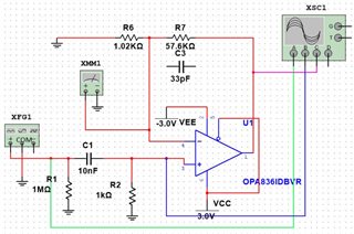
             schematic in TINA-TI    

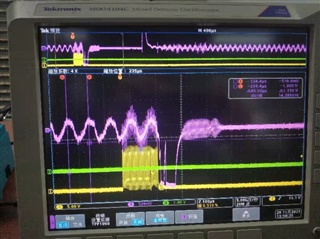
        Left part is the output with PD linked to GND; right part is the PD with postive power supply. and one interesting thing is that in normal power-mode, if we have no input signal, the output also performance bad.                                           

BR

Brandon

  • Hello Brandon,

    1. Power down pin for this device must be driven, low sets the amplifier in low-power mode and high sets the amplifier in normal operation. The power down pin needs to be driven to or above Vs- + 2.1V for normal operation, and at or below Vs- + 0.7V. For a +3.0/-3.0V, the enable threshold would be above -0.9V and disable threshold would be below -2.3V. A pullup resistor below 100kOhms is recommended for an amplifier in split-supply configuration. Also, I would highly suggest decreasing the split supply range from 6V to below 5.5V. The abs max rating for this device is Vs- to Vs+ of 5.5V. Continuous operation at higher than rated in the specified abs max rating might have destroyed the device. 
    2. Power down pin driven to ground would enable the amplifier. With no input signal, is this pin floating or terminated to a 50Ohm ground? 

       We also have an EVM available for the OPA836 located at this link.

    Thank you,

    Sima