Other Parts Discussed in Thread: LM393LV, TLV4021, TLV7021, LM393
Hi,
We are looking to use LM393BIDDR in one of our applications. The device is used as follows:
- IN2+ is connected to 2.5V
- IN2- is connected to external logic and can be either 0V or 3.3V
- OUT2 is PULLED UP to 3.3V using 100K pull up.
We are looking to power the chip using 3.3V. When doing some bench testing - we observe the following behaviour:
(a). When IN2- is 0V -> OUT2 -> 3.3V (this is expected)
(b) In certain instances when IN2- is 0V -> OUT2 -> 0 (this is not expected behaviour)
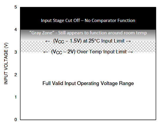
Looking at the data sheet there is a footnote (1) on Table 6.7 (Page 6/52)- "The voltage at either input should not be allowed to go negative by more than 0.3V otherwise output may be incorrect and excessive current can flow. The upper end of the common-mode voltage range is limited by Vcc-2V. However only one input needs to be in the valid common mode range, the other input can go upto maximum Vcc level and the comparator provides a proper output state. Either or both inputs can go to maximum Vcc level without damage".
A couple of questions:
1. Can the device in our application be operated at 3.3V? The datasheet seem to suggest operating voltage between 2V-36V but due to footnote (1) above .. we think that our application will be encountering conditions where both inputs could see voltages exceeding Vcc-2V and hence the output will function correctly?
2. Will the issue be resolved if the device is powered using 5V?
thanks
regards, Rsm