This thread has been locked.

If you have a related question, please click the "Ask a related question" button in the top right corner. The newly created question will be automatically linked to this question.

LMH3401: Inquiry about a reference design for ADC driver

Part Number: LMH3401
Other Parts Discussed in Thread: ADS54J60, , TSW54J60EVM

Hello,

My customer got a reference gudie on the ADS54J60 input design from ADC forum as below link.

https://e2e.ti.com/support/data-converters-group/data-converters/f/data-converters-forum/1066975/ads54j60-inquriy-about-adc-input-reference-design/3947657#3947657

The LMH3401 is used for ADC input in the TSW54J60EVM introduced in the link.

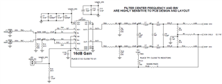
The customer is not sure that the above circuit can receive the DC siganl the customer wants to receive.

Could you please suggest an ADC input driver design so that they can receive the DC signal using the LMH3401 or other differential amplifier?

Thank you.

JH

  • Hello JH,

      Is the signal limited to DC? If so, is there another reason the customer is using an ultra high speed ADC such as the ADS54J60? Precision parts might be more applicable for the customer's design.

      I am unsure of the specifics of this ADC, but a quick glance at the datasheet shows a bandpass filter at one of the options/inputs of the ADC. Also, there seems to be a DC correction block which might be interfering with your DC signal.

       Amplifiers are paired with ADCs to easily convert single to differential, gain signals, provide variability in gain, level shifting to match input range of ADC, active filtering, impedance matching pre ADC filtering, and/or isolation (as a buffer). For testing with DC signals, a differential signal with filtering noise (rather than anti-aliasing since this is a DC signal) should have sufficed as a input design. Resource for this can be found at this link. But, an amplifier for this specific application can be necessary for avoiding loading the source due to input stage of the ADC. The LMH3401 does pair with this specific ADC due to its high bandwidth, high slew rate, and low distortion.

      Not sure though if an amplifier will help in this case for the DC signal, it is most likely the settings on the ADC. Make sure the DC offset correction is not in place (9.1.4.1 in ADS54J60 datasheet), and the input to ADC is a LPF and not BPF as shown in Figure 60 (ADS54J60 datasheet). But, again, it might be best to switch to a precision ADC. If customer is open to the switch, I can move this thread from high speed amplifier group to precision ADC group. 

    Thank you,
    Sima 

  • Hello Sima,

    Thanks for your reply.

    The customer should receive and analyze the about +/- 500mVp-p differential DC input signal below.

    For this, the ADC needs 14bit or more and 1Gsps sample rate to get the data they want.

       * Positive & Negative dc input capture image(Yellow signal)

    They think that in order to receive the above DC signal normally from the ADS54J60, it should be VCM 2.0V without DC block circuit. Is it correct?

    Could you please provide a more detailed guide for this circuit configuration?

    Thank you.

    JH

  • Hi Jh,

    this is definitely no DC signal, but an AC signal Relaxed So AC coupling could work.

    Please tell us more about the yellow signal. What is the repitition rate of the narrow pulse that can be seen in the scope plots?

    Kai

  • Hi Kai,

    The yellow signal in the capture image is a DC signal with noise added and the customer says they need to analyze DC level in the narrow pulse of the yellow signal.

    Will the ac coupling work without any problems?

    Would it be ok if I didn't change the VCM to 2.0V to input to the ADS54J60?

    Regards,

    JH

  • Hi Jh,

    if the customer intends to analyze the amplitude of narrow pulse of the yellow signal, or "needs to analyze the DC level of narrow pulse" as you would say, then he needs an amplifier which is able to quickly follow the yellow curve. And the amplifier must be able to drive the ADC and fully settle within the 150ns time window of narrow pulse. So the amplifier must be very fast and does work as an AC amplifier.

    May I repeat my question: What is the repitition rate of the narrow pulse that can be seen in the scope plots?

    I ask this question because for a successful AC coupling the repetition frequency must be higher than the corner frequency of AC coupling. So please tell more about the signal of yellow curve.

    Kai