This thread has been locked.

If you have a related question, please click the "Ask a related question" button in the top right corner. The newly created question will be automatically linked to this question.

TLV1704: Vpullup other than Vsupply

Part Number: TLV1704
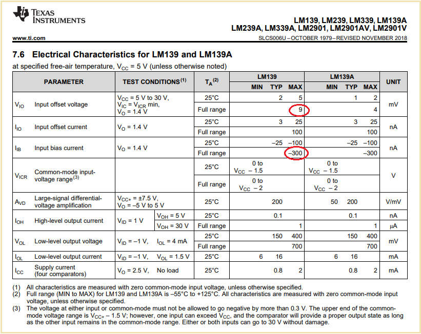
Other Parts Discussed in Thread: LM139, LM239

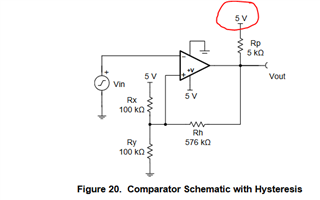
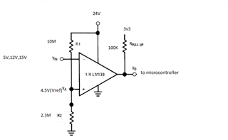
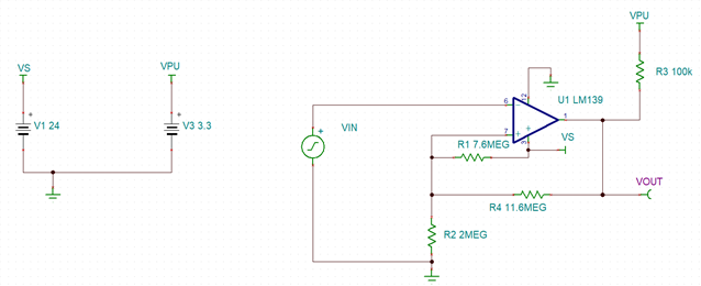
Referring to above image, My supply voltage is different(+24V), I want to make Vout compatible to microcontroller interface(+3v3). can i connect pullup resistor to 3v3, so that i can easily interface with  microcontroller ?

  • Hi Mohammed,

    yes, the front page of datasheet explicitely says that you can do this.

    Kai

  • Hello Mohammed,

    As Kai said, yes, you can pull-up to a voltage below the comparator supply voltage. 3.3V is fine.

    Puling up to a voltage below the comparator supply voltage is true of pretty much every open collector/drain device.

    However, not all can be pulled above the supply voltage. So careful reading of the datasheet, particularly the Abs Max table, to ensure the output can be pulled above supply.

  • Thanks mate. That was so informative for me.

  •  This is a simple circuit to sense whether a voltage is present/ not present.  If present, it will give 0, if not present, it will be high. My common reference is 4.5V, Using different opamps in the IC, i will connect each one inverting input to 5V, 12V,15V, 24V. My supply is 24V, my output pullup is connected to 3v3. 

    Need assistance.

    1. Can you review the schematic. I'm using LM239DR2G, because of no stock for TLV1704.

    2. How do i add hysteresis

    3. what things i should take care of in design ?

  • Hi Mohammed,

    We have reviewed your schematic and we would like to make a couple of adjustments to resistor values to implement hysteresis.

    As the simulation above depicts, we set your hysteresis thresholds to toggle low at ~4.8V and toggle high at ~4.4V.

    If you would like to adjust the simulation please download the Tina Schematic below.

    LM139_Voltage_Monitor.TSC

    We can adjust the threshold values depending on your needs.

    Please let me know if you have any questions or need further clarification.

    If you need more information on how to implement hysteresis for an inverting configuration, please access this cookbook: https://www.ti.com/lit/SNOA997 

    Best Regards,

    Joe

    Applications Engineer

    Linear Amplifiers Business Unit | Comparators Product Line (CMPS)

    All information in this correspondence and in any related correspondence is provided “as is” and “with all faults”, and is subject to TI’s Important Notice (http://www.ti.com/corp/docs/legal/important-notice.shtml)

  • Thanks for the suggestion. I will consider it. Since I'm using all 4 opamps for four different supply detection, can i have common resistor divider(r1 and r2) which can be used as a common reference for all 4 opamps on the PCB or should i have physically different resistors for reference and hysteresis for all 4 opamps. In that case, lets say If one of the supply(12V) goes down, will it effect the other outputs ?

  • Hi Mohammed,

    you would need different R1 to R4 for each comparator.

    Also keep in mind that the LM139 shows a much higher input bias current compared to the TLV1704. So while you can choose resistors in the MOhm range for the TLV1704, you should take resistors in the 100kOhm range for the LM139.

    Kai 

  • Ok. help me out here to understand it better.

    The Input bias current(Ib) flows into my resistor and produces voltages if my resistors(source) are in Mohms, which disturbs my references and my measured voltage , Is my understanding correct. ?

    R1 , R2, R4, same values as shown in simulation by Joe vanacore, i will convert it to Kohm range. Is that Ok?

  • Hi Mohammed,

    The Input bias current(Ib) flows into my resistor and produces voltages if my resistors(source) are in Mohms, which disturbs my references and my measured voltage , Is my understanding correct. ?

    Yes. I would decrease the resistor values by a factor of 10 when taking the LM139.

    Kai

  • Hello Mohammed,

    The bias current, about 25nA, flows OUT of the input pin towards ground. So this current will generate a voltage across any resistance in series with the input. So a 1M resistor would generate 1Meg*25nA=25mV.

    As Kai said...reduce the resistor values by a decade (or more)..

  • Will adding a series resistance(for Eg: Rs= R1 || R2) at input side with Vin(inverting terminal) will reduce the voltage which is generated or lowering resistor values is a better ?

  • Hi Mohammed,

    I usually choose the resistances in my circuits in such a way, that the error caused by input bias current is less than the error caused by the input offset voltage. Here, this is the case when the resistance seen by each input is less than

    R = 9mV / 300nA = 30k

    Adding a resistor in the same range or something below at the -input will furtherly decrease the error then.

    But it always depends on your application. If you can tolerate a bigger error and small current consumption is what counts in your application, you can increase the resistor to some degree. Then, you can furtherly decrease the error a bit by keeping both resistances seen from the inputs of LM139 identical.

    The input bias current cancellation resistor works the better the smaller the input offset current is compared to the input bias current. So it's always necessary to have a look into the datasheet of comparator to see how to proceed.

    The input bias currents of CMOS comparators are mainly ultra low leakage currents where such an input bias current cancellation resistor would make no sense.

    Of course, there's more to be considered when choosing the resistors arround a comparator. The performance especially at higher frequencies suffers from too high resistances, because parasitic impedances like stray capacitances and input capacitances of comparator begin to show a negative impact. High frequency circuits can even become instable with too big resistors. Also, choosing low resistances makes the circuit less immune against capacitive stray coupling from 60Hz electrical fields and other sources.

    Having said this, installing a resistor in the 100R or 1k range in series to the -input (or +input, if this is the input of your circuit) is recommended for many reasons. It provides a current limiting when the input sits on a wrong and dangerous potential. It limits the current into the comparator (input capacitance) when the input signal has steep edges. It can isolate the source from the input capacitance of comparator. It can dampen parasitic LC resonances at the input. It can provide some low pass filtering in combination with the input capacitance of comparator.

    Kai

  • Thanks mate.

    1. One quick question to avoid reading confusion. When you say choosing resistances, you follow R = 9mV / 400nA = 22.5k (in my case LM239), are you suggesting my R1,R2 should be choosen such that they are less than 22.5K?

    2. Also i'm adding a resistor of 1k as you suggested in series with Input voltage near to inverting input. In simulation is it possible to see the possible outcome?

  • Mohammed

    Yes, you're understanding of Kai's response is correct.  By choosing resistor values that are smaller will further reduce offset error that can be caused by input bias current.

    In regards to the addition of a 100 to 1k resistor on an input that comes from some place else in your system is a very good suggestion.  Simulation will not really show much because the model doesn't showcase a varying input bias current based on input voltage.  The key is understanding that the resistance will limit the current if the input voltage goes outside the recommended range.

    Chuck

  • Hello Kai,

    Thank you for providing all of this information showing the how lowering the resistor values reduces the input offset error. 

    Mohammed, 

    Please reach out if you have further questions.

    Best Regards,

    Joe

    Applications Engineer

    Linear Amplifiers Business Unit | Comparators Product Line (CMPS)

    All information in this correspondence and in any related correspondence is provided “as is” and “with all faults”, and is subject to TI’s Important Notice (http://www.ti.com/corp/docs/legal/important-notice.shtml)

  • Hi Mohammed,

    I want to briefly explain what we see in the simulation:

    The circuit was reduced and simplified to demonstrate the impact of input bias current on the offset voltage only. So the comparator was removed and only the input bias current, the feedback resistors and the logic output voltage state is present in the simualtion. The two circuits on the left show the situation when the output of comparator emits low level and the two circuits on the right when the output transistor is turned-off and the comparator emits high level, due to the 10k pull-up resistor. Each of these circuits on the left and on the right show two scenarios with zero input bias current and 400nA. The additional input offset voltage generated by the input bias current is simply shown by VM1 and VM2.

    The input bias current of comparator is simulated by a current source which is connected with the (cold) end to signal ground and with the other (hot) end to the node where the +input of comparator is normally being connected to. By this, the direction of simulated input bias current is identical to the direction of real input bias current of comparator, which is flowing out of the comparator because of the internal PNP transistors in the input stage.

    Kai

  • Hi Kai, 

    Thank you for all of this explanation and information. I think that it will really help Mohammed :)

    Mohammed,

    Please reach out with any additional questions on the above posts. 

    Best Regards,

    Joe

    Applications Engineer

    Linear Amplifiers Business Unit | Comparators Product Line (CMPS)

    All information in this correspondence and in any related correspondence is provided “as is” and “with all faults”, and is subject to TI’s Important Notice (http://www.ti.com/corp/docs/legal/important-notice.shtml)

  • Hi Mohammed,

    I have not heard back from you for quite some time. I will now close this thread. If you have further questions please respond in this thread or create a new one.

    Best Regards,

    Joe

    Applications Engineer

    Linear Amplifiers Business Unit | Comparators Product Line (CMPS)

    All information in this correspondence and in any related correspondence is provided “as is” and “with all faults”, and is subject to TI’s Important Notice (http://www.ti.com/corp/docs/legal/important-notice.shtml)