Part Number: OPA855
Other Parts Discussed in Thread: TINA-TI, ONET4201PA
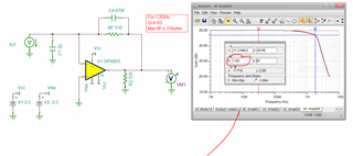
Attached Transimpedance amplifier circuit configuration, I would like you to briefly explain the role of RF and CF and how to determine the value.

・ Apply 3.8V to IN + (pin 4)
・ RF (feedback resistance)
Recognized that this resistance is for setting the gain (dB) of the amplifier doing.
・ CF (feedback capacitor)
This capacity is to prevent oscillation with a normal operational amplifier.
It is recognized that the phase of the feedback voltage is adjusted.
In this circuit, Is it for setting the cutoff frequency?
CF <= 1 / (2π ・ RF ・ FC)
Below, the application note is also for this circuit of OPA855 Can you use it?
Analog Engineer's Circuit: Amplifiers
JAJA549A–February 2018–Revised January 2019
(page 2)
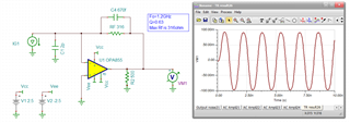
Fine adjustment of the value is due to the influence of the PCB layout.
Due to the influence of parasitic capacitance, etc.
I think that I will adjust it while observing the waveform by checking the operation on the actual machine, but I am consulting because I want to do some desk calculation.
We will wait for the answer.