Other Parts Discussed in Thread: LMH6321, , OPA551
Hi TI Technical Support Team,
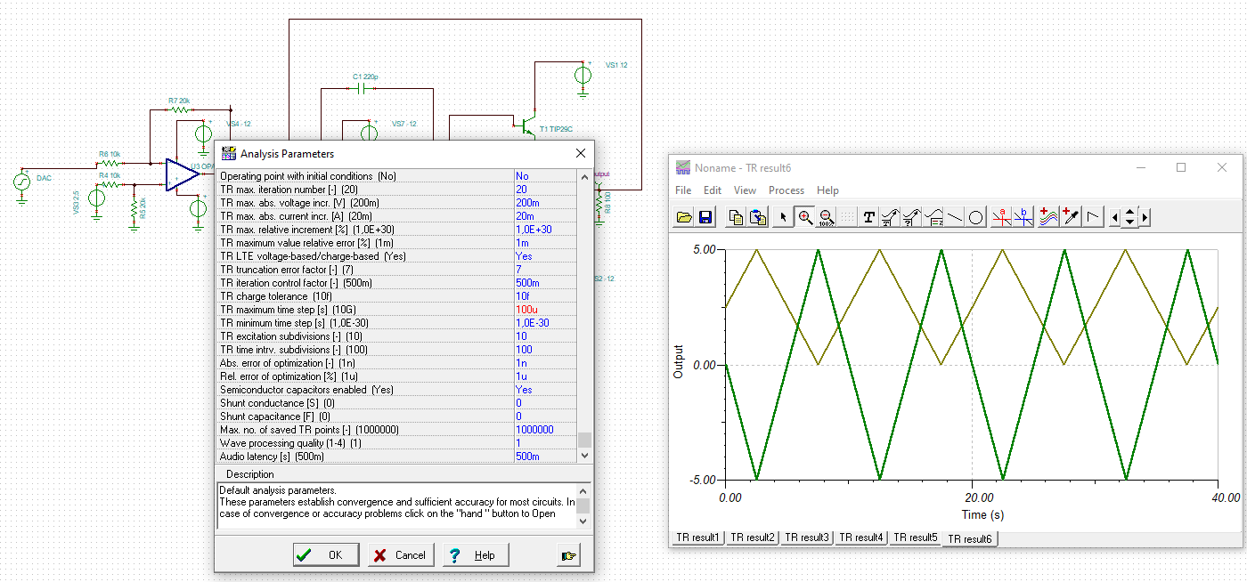
I am aiming to design a circuit that will be used to test for example battery. The circuit will apply +/-5V and also be capable of delivering +/-100mA (charge/discharge) to the load/battery. I am planning to use OPA2171 and boost its current using push-pull stage. I read some app notes and datasheets from TI and decided to use the method mentioned in OPA551 datasheet (Figure 30) to boost opa2171 output. I previously used LMH6321 high speed buffer, but right now I am searching for some discrete design and decided to use push pull stage. I attached the simulation setup to this thread. I have following questions.
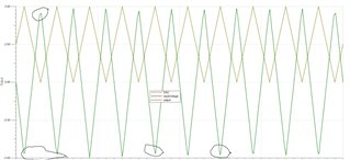
1. I saw some distortions and clamp in the pushpull output. I expect them to reach -5 or +5V, but clamping and distortion occurs. Could you please comment what is the possible reason for the distortion and how to eliminate it?
2. R1 (resistor between opamp output and pushpull output in simulation file) is used for current limit as far as I know. How should I calculate the proper resistor value to limit the circuit output current? The limit doesnot have to be exact, for example limiting to 120-130mA is also enough for me?
3. Is there any other suggestions you can make to improve opamp + boost stage?
Thank you for your help,
Best regards,
Ahmet