This thread has been locked.

If you have a related question, please click the "Ask a related question" button in the top right corner. The newly created question will be automatically linked to this question.

INA228: INA228 EVB

Part Number: INA228

Hi, 

I have a INA228EVM with me. 

It is loaded with the latest 

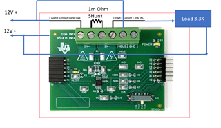
When I try to use the EVB, connect to the power supply IN+ and IN- with 12V supply and 1m Ohm Shunt resistor and a load of 3.3K

The result which I get is Inconsistent.   

Can I have a demo from one of your FAE's or Distributors on our EVB please. 

My VBUS is 12V but the result cvs has values starting from 1.5V to 99V

VSHUNT_Results_11_02_05.csv

Thanks and Regards

    Jeelani

  • It is loaded with latest firmware

  • Hello Jeelani,

    Thank you for using the TI forum.  This is very odd...  can you please send a picture/diagram of how you have connected your load to the EVM?

    We don't have a video demo for this EVM, but we do have a very detailed User's Guide: https://www.ti.com/lit/ug/sbou241d/sbou241d.pdf

  • Hi Mitch,

    Connections as above and the Shunt is 1m (milli) Ohm 

    The Settings screen shot of the tool. 

    Thanks and Regards

       Athiq

  • Hello Athiq,

    Thanks for sending that data. It looks like the problem is that the EVM GND pin is not tied to your system GND.  (This is usually done from the GND on the green header).  With out the GNDs tied together, the device has no point of reference, so VBUS is essentially a floating voltage, which is why you are getting very wrong data.

    Also, from the calibration section of the GUI you shared, it looks like you are using a full scale range of only 1mV, which is a very small percentage of the device full scale range.  This will make the VSHUNT data very noisy and less accurate.  To fix this, you will want to use a larger shunt resistor to better utilize the full scale sensing range. (Alternatively, if you are measuring more than 1A of current, then you'll want to put that maximum value instead of 1A).

  • Hi Mitch, 

    Thanks for the reply. 

    Can u use the -ve of 12Vdc as the ground reference for the whole system and hook up the GND on the green connector with -Ve 12VDC line?

    What shd be the ground if I am using a AC signal? 

    Thanks and Regards

        Athiq 

  • Hello Athiq,

    That may work, depending on your supply.  If your ±12V supply is floating, then you would be able to set the -12V as the system GND, making +12V an effective 24V above GND. This will affect the power/VBUS calculations as well though...  If your ±12V supply is not floating and has a set GND, like the EVM/MCU do (through the PC USB cable), then it wouldn't work on the EVM, as VBUS cannot go negative.  If you want to see an example of how this can be done with isolation, then you may be interested in this TIDA:  https://www.ti.com/tool/TIDA-00313, which uses a floating GND for the IC. 

  • Thank You Very Much Mitch. 

    Attached is the New Excel now. 

    All_Results_23_02_06.csv

  • You're welcome, glad I could help!