This thread has been locked.

If you have a related question, please click the "Ask a related question" button in the top right corner. The newly created question will be automatically linked to this question.

OPA2189: Paralleling 2 current sensing opamps

Part Number: OPA2189
Other Parts Discussed in Thread: INA826, TLV3502

Hi Team,

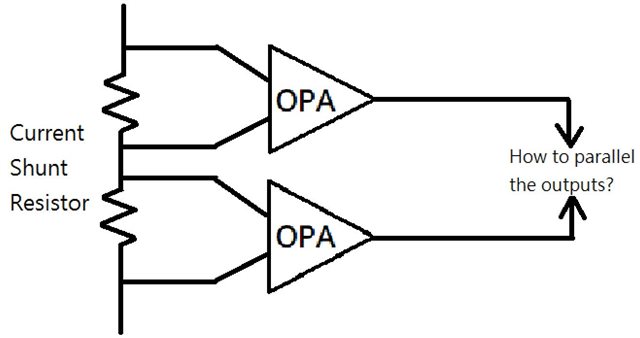
My cusotmer is surveying high accuracy current sensing solution for OCP(over-current protection) function, the OPA's output error needs to be < 2.4%(I think OPA2189 might be suitable), and this circuit has to deal with single fault conditon(when one OPA fails), so customer is wondering if paralleling the outputs of two OPA is applicable. Pls kindly help to suggest, thanks. 

  • Hi Charles, 

    The accurate way to sense differential current is using instrumentation amplifier. Please let us know the current level and if the current sensing is on the high or low side. 

    Regarding to the output error < 2.4%, Do you mean the Measured current/Actual current has to be better than 97.6% on each channel?

    What are you going to do with the parallel outputs? Do you want to use summing amplifiers to combine the two duplicated channels?

    What are the size of sensing resistors? The sensing resistors have an errors as well. What are the shunt resistance errors of the two identical sensing resistors?

    Please provide us additional requirements and we may come up a solution for the application. 

    Best,

    Raymond

  • Hi Raymond,

    1. The highest measured current level is 4.2A.

    2. Yes, the Measured current/Actual current has to be better than 97.6% on each channel.

    3. Since customer needs to address single fault conditon, which means when one OPA channel fails, the other OPA channel can still implement OCP function for the system. Under normal condtion, system will refer to the highest measured current between 2 OPA channels and determine if the OCP threshold is triggered.

    4.Sensing resistor has not been determined yet.   

  • Hi Charles,

    Enclosed is an example of a proposed design approach. 

    Two instrumentation amplifiers are used to sense current and convert it to voltage, then follow by a summing amplifier, where Vout = (Vout1 +Vout2)/2. Please note that low measurement current will impose higher %error in the system. What is the minimum current that you want to guarantee <2.4% errors? 

    If you provide me with additional details, such as shunt resistor values, Vcm of the current sensing system, cost etc., I can adjust the simulation per your requirements. 

    INA818 high side Isense 02222022.TSC

    Under normal condition, system will refer to the highest measured current between 2 OPA channels and determine if the OCP threshold is triggered.

    For this measurement, you may place a comparator between the two Vsensing output, and then the application will know the highest reading. 

    Best,

    Raymond

  • Hi Raymond,

    Current sensing is low side, maximum Vs supply is 35V, minimum OCP trigger point is 95W/24V=3.958A. Based on these conditions, do you have recommended current shunt ressitor value?

    According to your suggestion, configuration should be like below.

  • Hi Charles, 

    Based on these conditions, do you have recommended current shunt resistor value?

    I proposed 10mΩ shunt with 0.5W to 2W rating and 1% or better. The resistor dissipation is approx. 1mΩ*4.2^2 = 0.18W.

    Since this is low side of current sensing, it will be the best to use supply rails. I selected INA826 for your Vs of 35Vdc. INA826 is low in cost and it has the input over voltage protection up to ±40V. 

    In terns of circuit implementation, there are many options, below is an example, including the supply rail selections. 

    I am using our low cost automotive grade TLV2917-Q1 op amp as comparators, and it should switch fast enough for your application. You may also pick our TLV3502 or similar comparators or simply use general purpose op amps for the voltage comparisons. Regarding to the last stage, you can implement what you have with OR gate or as simulated. 

    I did check the four input scenarios, and it seems to be working:

    1. Both Isense circuits are working properly. 

    2. Vsens2 shunt is failed to convert I-to-V or not function properly

    3. Vsens1 shunt is failed to convert I to V or not function properly

    4. Both shunts are failed to convert I to V or not function properly.  

    I have not calculated the worst case error analysis. Once you finalize the application sensing circuit, you may confirm this part of requirements.

    Enclosed is the above Tina simulation. If you have any questions, please let us know.  

    INA826 low side Isense 02222022.TSC

    Best,

    Raymond

  • Hi Charles, 

    I hope that I have answered your inquiry. 

    I am going to close this thread. If you have additional questions,  you may still reopen the inquiry or you may create a new one via E2E forum.  

    Best,

    Raymond