This thread has been locked.

If you have a related question, please click the "Ask a related question" button in the top right corner. The newly created question will be automatically linked to this question.

XTR117: 4-20mA transmitter.

Part Number: XTR117
Other Parts Discussed in Thread: TINA-TI

Respected Sir/Madam.

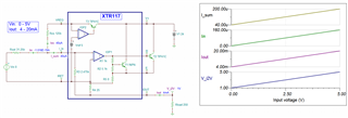
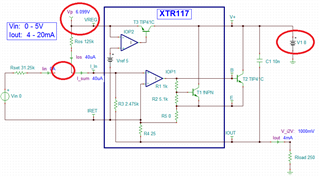
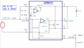
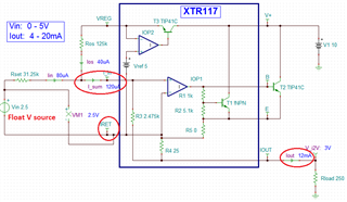
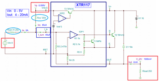
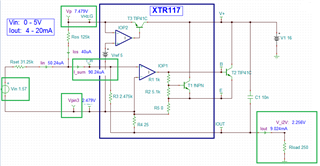
While testing the 4-20mA current transmitter after doing the connections as per the data sheet I could not get the variation in the current at the output, I was receiving a constant current on series with the Load Resistor. 

Please provide a basic testing circuit with component values.

Thank You, 

Koustubh.

  • Hi Koustubh,

    can you show a schematic of your circuit?

    Many users overlook that the IRET pin of XTR117 is floating and must not be connected to the ground of VLOOP.

    Kai

  • Kai, 

    I have attached the circuit schematic which I had used. 

    Thanks.

  • Hi Koustubh,

    and how have you generated and wired the input voltage?

    Kai

  • Hi Koustubh,

    Kai has pointed many references over the E2E forum on the XTR117 or 2-wire 4-20mA transmitter topics and application. 

    Enclosed is a simulation in Tina-TI. The input is 0-5Vdc and a linear V-to-I conversion is directly proportional to the output current from 4-20mA, and at the output with R_load of 250Ω, it converts 4-20mA current loop back to 1-5 Voutput in voltage (4mA * 250Ω to 20mA*250Ω ).

    XTR117 0-5V 4-20mA 02232022.TSC

    If you need further assistant, please let us know. 

    Best,

    Raymond

  • Hey Raymond,

    I tried the same circuit at my side. but did not get satisfactory results of the 4-20mA transmitter.
    All values were used similar to what you had sent still I'm getting an constant current at the output i.e. 7.12mA.
    Also as you have shown the test points at VREG and  V_i2V where I should get 6.1V and 1V respectively I'm getting 24Volts at both these points. 
    Also the current Iout has no change even if the Vin Is changed from 5V to any other value.   

    I also simulated the circuit you had shared and that worked completely fine on the simulator but could not work on the hardware.
    Please suggest changes or additions if any.


    Thank you.

    Regards,

    Koustubh,

  • Hi Koustubh,

    hhm, the best idea is to take a fresh XTR117 and fresh TIP41C and check again. Also check that the circuit is wired correctly. Some users did wire the TIP41C incorrectly in the past.

    By the way, I remember that someone had issues when the decoupling cap of XTR117 was omitted. So please add a 10nF cap between pin 7 and pin 4 of XTR117 as shown in figure 1 of datasheet.

    Kai

  • Hi Koustubh,

    at VREG and  V_i2V where I should get 6.1V and 1V respectively ...

    Please get a new XTR117 and replace the existing XTR117. The VREG node should get 5Vdc. Please start with 7.5-10Vdc from the power source, instead of 24Vdc. Once it is working, you can crank the input voltage. The XTR117's internal regulator has to work at 5Vdc. 

    (simulation has to use V1 = 10Vdc or higher with all the connection). 

    If you break the input after Rset or 31.25k, you should get 4mA constant current out. The internal current gain of the circuit is 100, where 40uA*100 = 4mA should be sourced at the output Iout or pin4. 

    Instead of break the input connection, it will be easier to remove the power source from the input, see the image below. 

    The following input is very important. Vin is the input power source, 0-5Vdc power source has to be floating. 0-5Vin voltage source has to be measured with respect to Pin3 or IRET  node. It won't work if Vin is referenced to ground. As it is simulated, the ground is on the Vloop power source side or 8Vdc in this case. 


    The current as simulated is increased to 120uA (40uA + 80uA), with the current gain of 100, the pin3 should source 12mA. 

    Please try this out and see if it works better now. 

    Here are two 4-20mA application notes and bench testing results in case that you are interested. 

    https://www.ti.com/lit/ug/tiduao7/tiduao7.pdf?ts=1645717525310&ref_url=https%253A%252F%252Fwww.google.com%252F

    https://www.ti.com/lit/ug/slau526/slau526.pdf?ts=1645717708377&ref_url=https%253A%252F%252Fwww.google.com%252F

    Best,

    Raymond

  • Hi Raymond,

    I have tried this circuit with a new IC and a New Transistor too.

    Currently I'm testing the circuit with Rset =33 Kohm and Ros as 127 Kohm.

    load 250 Ohm

    I got the following results.

    (Results with no input connected.)

    1.  VREG = 6.17 Vdc

    2. V_i2v = 1.01Vdc

    3. I_sum= 900uA

    4. Iout = 6.31mA

    Whenever I connect the Input i.e. 0-5 Vdc the values of VREG & V_i2v gets changed and there is no change in the output current. 

    Also when I change the input 0-5 Vdc there is no change in the output current.

    Please tell solutions to overcome this. 

    Thank you.

    Regards,

    Koustubh.

  • Hi Koustubh,

    the XTR117 is such a nice and stable chip. Something must terribly go wrong with your setup. So please post a complete schematic, your layout and a photo of your setup.

    And have you added the 10nF cap I asked you for?

    Kai

  • Hi Koustubh,

    As Kai indicated, something in the setup is gone wrong. Here is what I'd like you to do, in addition to post the complete schematic and setup photo and/or layout.

    Please make sure Ros = 125kΩ and Rset = 31.25kΩ. If you do not have these, please find two of 250kΩ and 62.5kΩ, and parallel these resistors to make up these values. Or you can place two resistors in series and make up these values. 

    Setup 1:

    1.  Without input voltage Vin = 0 or short the input Vin or disconnect the Vin. 

    2 . Vp = 6.1Vdc and V_i2V = 1.0V over 250Ω load, where Iout = 1.0V/250Ω = 4.0mA.

    3. I_sum = 5V/125kΩ = 40uA, where IRET pin or Pin3 should read approx. 1.1Vdc. 

    Setup 2:

    1.  With input voltage Vin = 1.57Vdc with a brand new dry cell battery (AA, AAA or others) and input is floating. 

    (note: not all brand new dry cell will read 1.57Vdc, but it is not important, I just want to the data from the Vin figure, please record battery's Vin value). 

    2 . Vp = 7.48Vdc and V_i2V = 2.26V over 250Ω load, where Iout = 2.26V/250Ω = 9.04mA approximately. 

    3. I_sum = 40uA + 50.24uA = 90.2uA where IRET pin should read approx. 2.48Vdc. 

    Please let me know what you measured from your setup. The data you provided may mix up with different input conditions. I can not interrupt it properly. 

    Best,

    Raymond

  • Hello Kai and Raymond.

    Finally my Issue as been resolved and I'm getting appropriate outputs now.

    The actual fault was of my Multimeter which gave the wrong current readings.

    The device showed correct voltage values but it gave absolutely irrelevant Current values, which caused a major issue.
    Thank you for your assistance and support. 

    Thank You.

    Regards, 

    Koustubh.

  • Hi Koustubh,

    happy to hear that it wasn't the XTR117 Relaxed

    Kai