Hi,
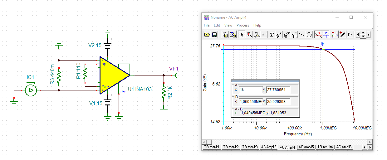
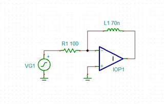
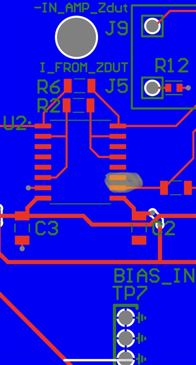
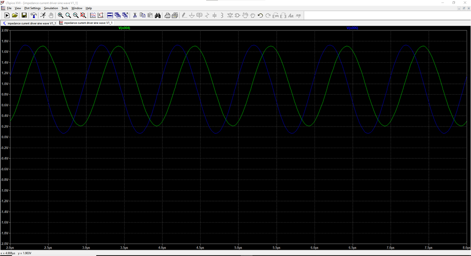
I'm trying to build an instrument to measure small inductances as part of a school project. The circuit drives a sine wave through a sense resistor and an unknown inductor. The INA103 amplifiers are used to convert the differential voltage across a 10 ohm sense resistor and across the unknown inductor (range of 50-80nH) into single ended measurements so that they can be digitized with an ADC. I've simulated the circuit in LTSpice, and the model yielded the desired outputs. I used Altium to design the PCB and had it manufactured by JLCPCB.
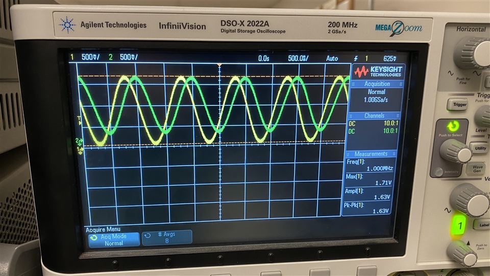
When the board arrived, I measured the outputs from the INA103 instrumentation amplifiers using an oscilloscope. The input signal is a sine wave, 1MHz, 900mVpp with a 460mV DC offset. I was expecting to see sine waves with amplitudes in the range of of 1.5V to 1.7V and a DC offset of 0.75V to 0.9V. Instead, I see sine waves with an amplitude of roughly 160mV and a DC offset of 12.3V. I don't understand where the large DC offset is coming from.
I'm supplying the amplifiers with +/- 15V.
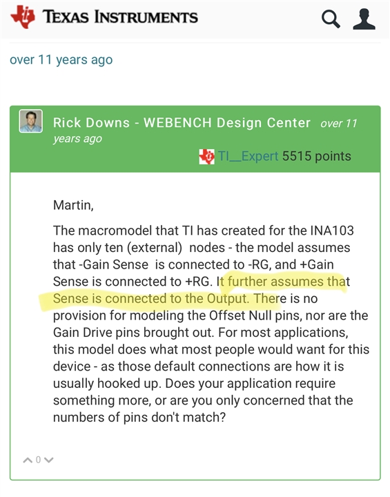
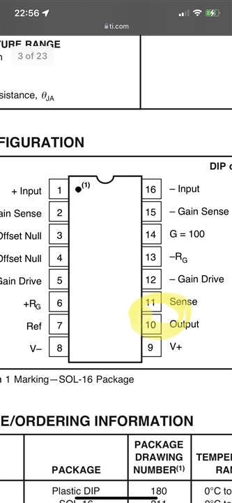
Where did I go wrong? Is the SPICE model inaccurate? Did I fry the amplifiers when I soldered them onto the board? Did I make some sort of hard error in my PCB? Images attached. I can provide many more if it would be helpful.
Thanks for your help!