This thread has been locked.

If you have a related question, please click the "Ask a related question" button in the top right corner. The newly created question will be automatically linked to this question.

INA234_236EVM: threshold setting

Part Number: INA234

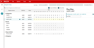
In INA234 eval. Board, there is one option to set the alert limit in one of the register. Customer tried it by entering 2’s complement number but no luck. Below is the screenshot for reference. For some of the functions they get peak current of more than 3A for which voltage drop is almost more than 60mV. So to set threshold values of 40mV what is the value I should set in alter limit register?


  • Hi Prahlad,

    In order for the ALERT pin to toggle when shunt voltage is over 40mV, the LIMIT register should be programmed with 0x3E80. Also FLAGS register (0x6) “Shunt Overlimit” bit should be set to ‘1’, which is the case in the attached picture.

    However if the inputs are connected such that the shunt voltage appears as negative value, the LIMIT register should be written with 0xC17FF or 0xC180. FLAGS register “Shunt Overlimit” bit should be set to ‘0’ while “Shunt Underlimit” bit set to ‘1’.

    Regards, Guang

  • Hi Guang,

    Thanks for the reply!

    what is the min. time by which alert reg. is updating? Because i can see even though Vshunt is crossing set threshold on multiple positions i cannot see proper toggling of the bit in flag reg. I have set the auto read to asa fast as possible in the GUI

  • Hi,

    When an overvoltage event is transient in nature, it may not be caught 100% of the time if the pulses are narrow. The overvoltage magnitude, relative to the threshold, also plays a role. Besides, there is going to be a delay in the alert pin response due to the conversion time of the device. Here is a picture illustrating the range of response time.

    These test cases use a step function as overvoltage input. As you can see, it takes anywhere between 1 and 2 conversion times for the ALERT pin to respond after the overvoltage event occurs. If the pulse is less than 2x conversion time, there is a possibility that it will be missed. It should be noted that this is for situations where the overvoltage amplitude is close to, but just above the threshold. If the overvoltage amplitude is much higher, then the delay should be shorter. But will be 1x conversion time at a minimum.  

    You may refer to the datasheet section 8.2.2 for more discussion on this topic.

    Regards, Guang

  • When I am making LEN to latched state i can see toggling of the flag reg properly. May I know the reason for this?

  • Hi,

    When the ALERT pin is in transparent mode, it clears when the overvoltage event goes away. When it in latched mode, the ALERT pin stays in triggered state even when the overvoltage event disappears. This is probably why.

    Regards, Guang