This thread has been locked.

If you have a related question, please click the "Ask a related question" button in the top right corner. The newly created question will be automatically linked to this question.

TLV521: TLV521

Part Number: TLV521
Other Parts Discussed in Thread: TINA-TI, LPV521, OPA2991

Dear Sir/Madam

In section 8.1.1 of the datasheet it discusses driving capacitive loads. There is Table 1 that states in unity gain configuration a 50pF load requires a 154k isolation resistor (Riso). However a 10nF capacitor requires a much smaller Riso of 13.3k? This makes no sense, why would a larger capacitor need a smaller series isolation resistor. Is there a block diagram or tutorial somewhere on these micropower op amps as they seem to have peculiar behaviour?

Br

Edward

  • Hi Edward,

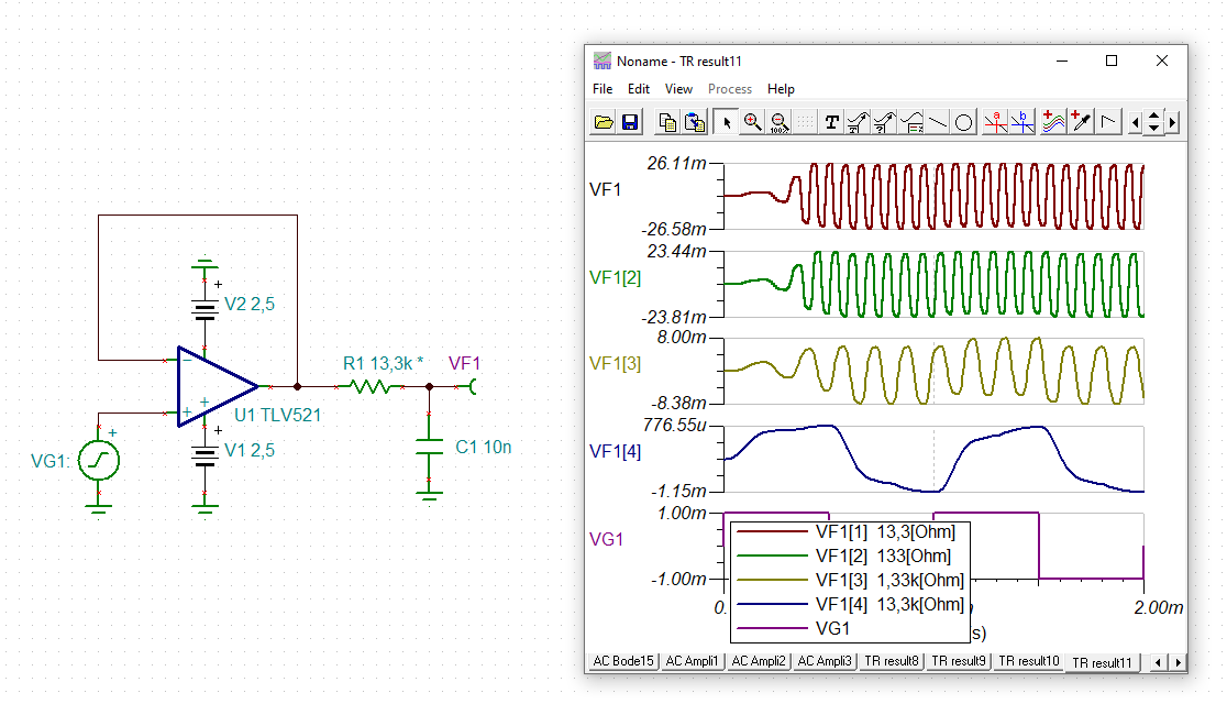
    well, it's true:

    edward_tlv521.TSC

    Kai

  • Hey Edward,

    The isolation resistor decreases in size as the capacitor increases because of the location of the pole created. Typically large cap loads should not be driven using the micropower amps. The location of the pole is determined based on the output impedance of the op amp and the isolation resistor size.

    Here is a resource for the theory behind the isolation resistor sizing.

     Solving_Op-Amp_Stability_Wells_6-5-12.pdf

    Best,
    Jerry

  • Ok thanks but it doesn't really explain what's going on inside the op amp. Do you have behavioural model i.e. a simplified model of the op amp, so I can get a feel and understanding what is going on?

  • Hey Edward, 

    We have a model available on the product page: 

    Is this what you mean? 

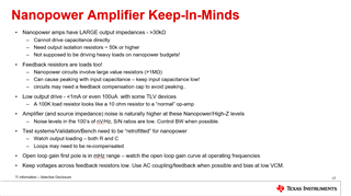
    I also have a training slide for nanopower op amps if it is useful to the understanding: 

    All the best,
    Carolina 

  • Hi Edward,

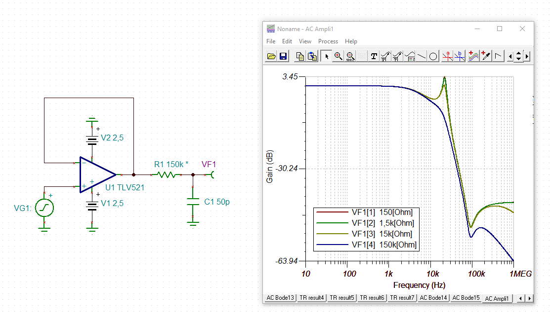
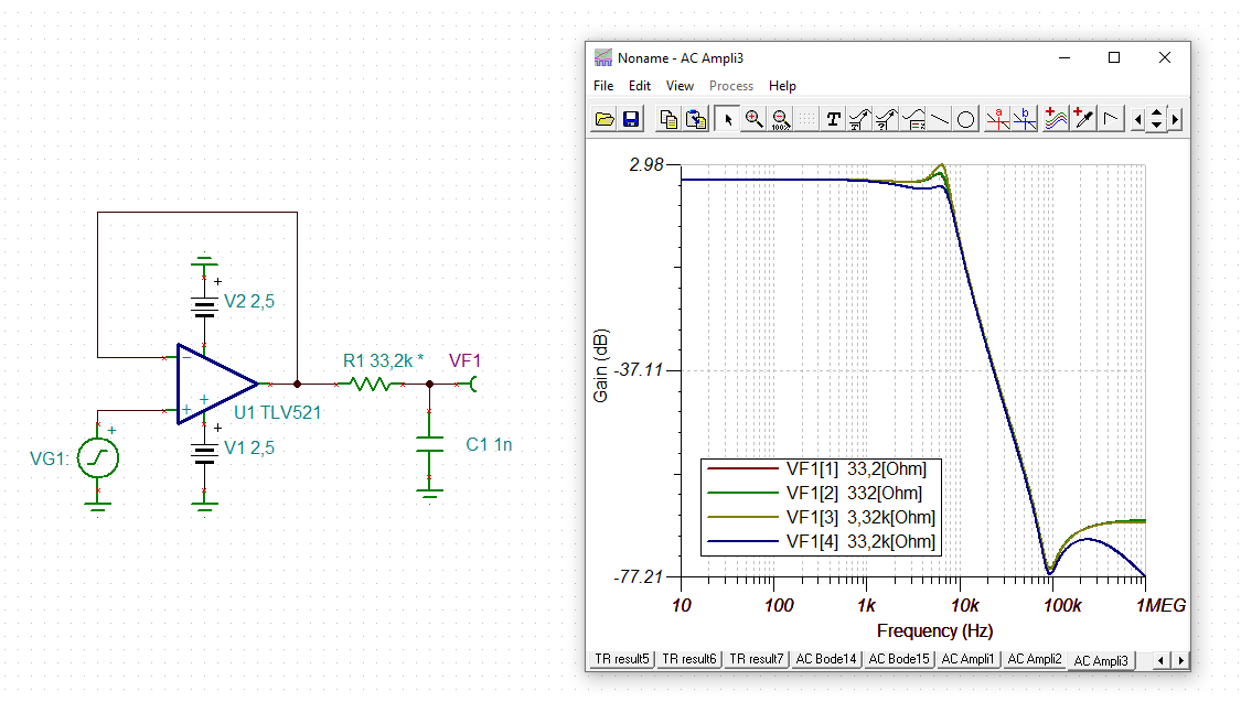
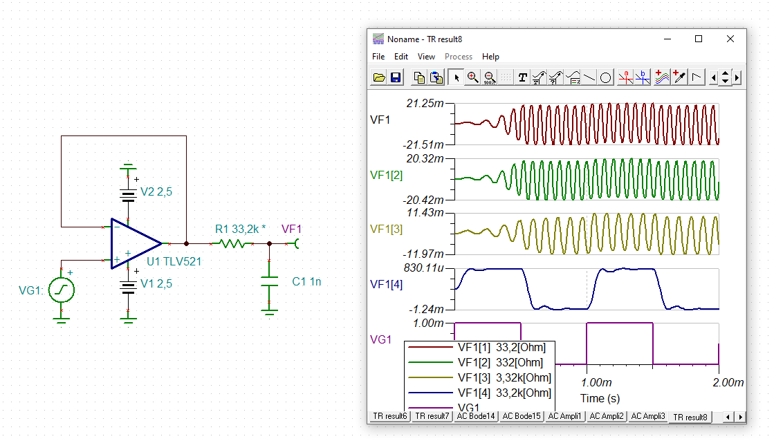
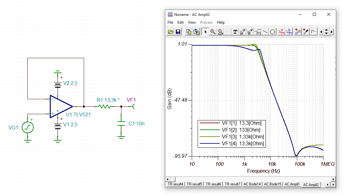
    nanopower OPAmps are designed to draw ultra low supply current. Some compromises have to be made to achieve this. Unfortunately, the open loop output impedance of TLV521 looks highly inductive (0.8...0.8H). This inductance resonates with any external capacitive load and destabilizes the OPAmp by introducing a gain and a heavy phase interference into the feedback loop. This will ruin the phase margin and cause oscillation. To keep the OPAmp stable, this resonance has to be damped by introducing a suited dampening resistance. To dampen a LC series oscillation, R has to fullfill the relation:

    R > SQRT(2L/C)

    So, when C decreases R has to increase and vice versa, provided L is almost constant.

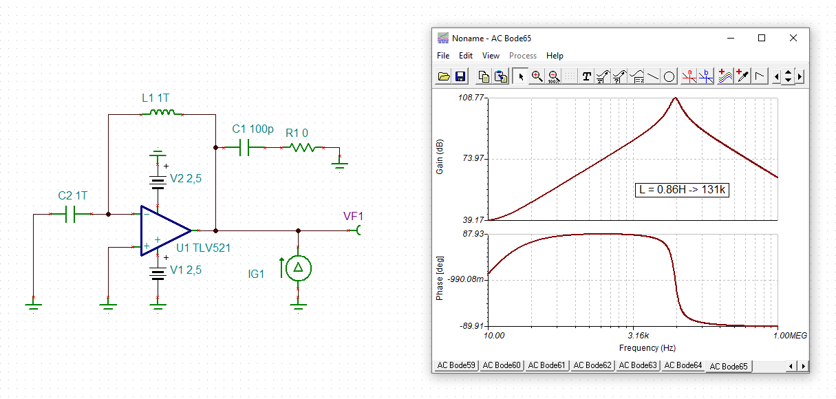
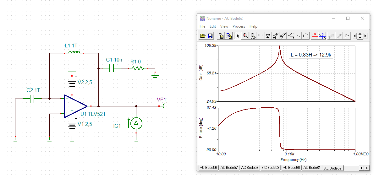
    The following TINA-TI simulation shows the open loop output impedance of TLV521 when adding an external load capacitance of 100pF:

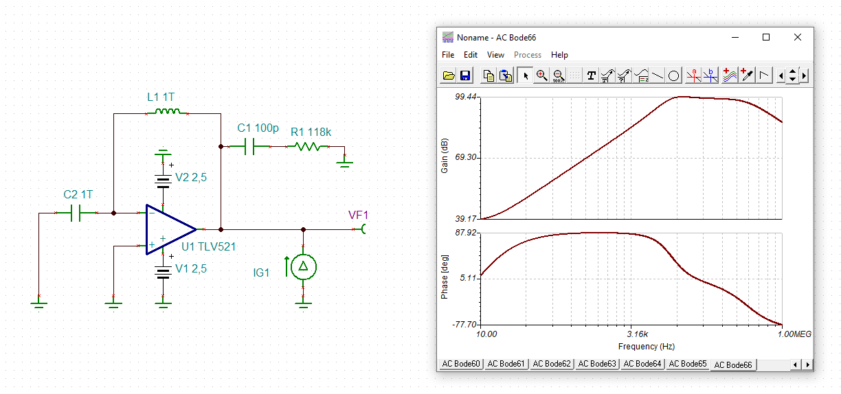
    The LC resonance can clearly be seen from the phase response and the sharp phase jump from 90° to -90°. By the help of Thomson formula the inductance can be estimated to about 0.86H. And from the above relation R can be estimated to fully dampen the resonance. I get 131k which is very close to the 118k given in datasheet:

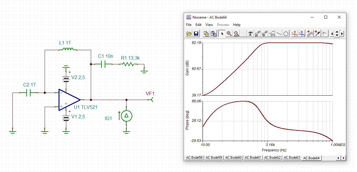
    And here for a capacitive load of 10nF:

    edward_tlv521_30.TSC

    As you can see, to keep the OPAmp stable, the capacitive load together with the dampening resistance have to act as a snubber here. This explains why R has to increase when C is decreasing and vice versa.

    Kai

  • Kai

    Why are using 1 Terra Henry and 1 Terra Farad in the circuit?

    Br

    Edward

  • Hi Edward,

    these are representations of ideal components for L and C. For proper DC biasing there shall be a DC connection to make the TLV521 perform like a voltage follower. But at AC the OPAmp sees an infinitely high feedback impedance which allows to measure the open loop output impedance.

    The output impedance of OPAmp is measured by forcing an AC current into the output and measuring the output voltage. TINA-TI displays "VF1" referenced to "IG1" which gives the output impedance.

    Kai

  • Kai

    Ok got it you are breaking the loop.

    I also found this article (+) Designing with low-power op amps, part 4: Stability concerns and solutions - Analog - Technical articles - TI E2E support forums which explains that these nanopower op amps have very high output impedance, such that even a small capacitance loads the output and can cause enough phase shift to push it into oscillation,

    Br

    Edward

  • Hey Edward, 

    Was this issue resolved? Please let us know by clicking "This resolved my issue."

    In the meantime, I will close the thread. 

    All the best,
    Carolina

  • No. The other problem I am seeing is the data sheet just contains typical values and I need to know min max values over -40 to 125degC?

  • No. The other problem I am seeing is the data sheet just contains typical values and I need to know min max values over -40 to 125degC?

  • Hi Edward,

    the many figures in the Typical Characteristics" show the performance at varying temperatures.

    Kai

  • Yes but they are al typical, so how can you design with these, how do I know the min max?

  • Hi Edward,

    I think this has to do with the very low price of TLV521. You might want to have a look at the LPV521.

    Kai

  • Hey Edward,

    The way to approach designing with provided typical values is to take the statistical approach to generating an acceptable min/max. A good resource for this is the "Typical Specifications and Distributions" section in some of our datasheets. I use OPA2991 as an easy to remember example.

    Section 7.3.9 in the datasheet details how to guardband your design when using typical characteristics.

    We also discuss other guardbands in the TI precision labs. For example, in the Bandwidth video we say to allow 30% tolerance at room temp and an additional 30% across temperature.

    Best,
    Jerry

  • That is a really good write up and I have learnt something here Thumbsup

  • Only problem now is I am looking for a SOT23-5 footprint and the SC70 is smaller Disappointed

  • I am trying to replace the ISL28194 which is similar op amp

  • On the LPV5211 datasheet they state 'Temperature Extremes' but do not define what this means. I am sure it means -40 to +125degC but surely they should state it somewhere, or have I missed where they do this?

  • Hi both,

    yes, such a statistical approach may be reasonable for many cases. But for a professional product you will need maximum specifications. We sell a product with a board containing more than 30 OPAmps (all from TI by the way Relaxed). If only one OPAmp is marching to a different drummer, the whole board can be thrown into the rubbish container.

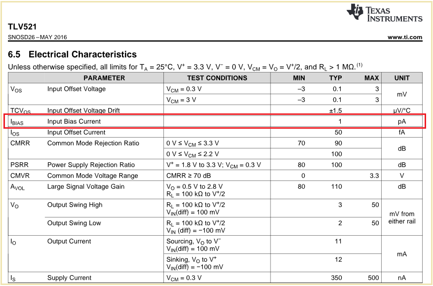
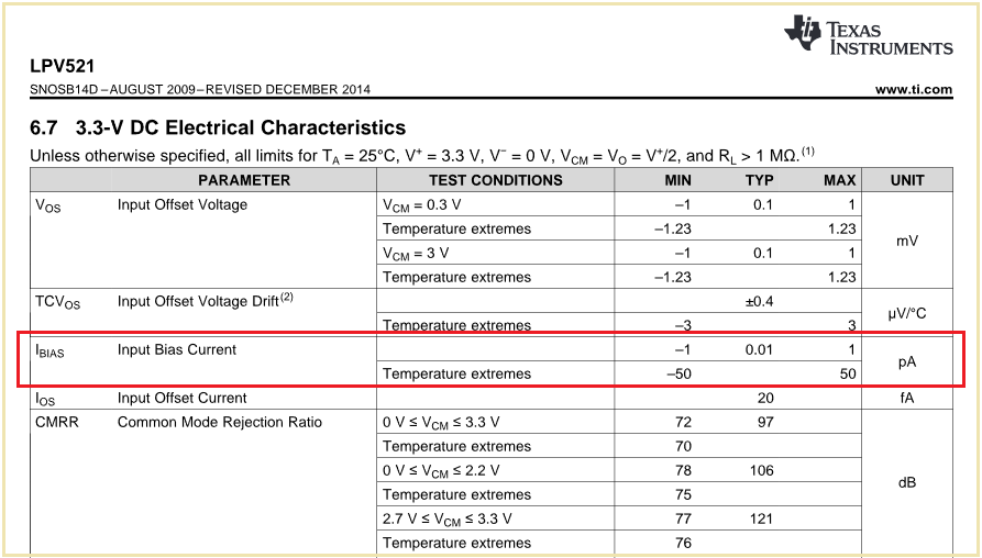
    Compare the datasheets of TLV521 and LPV521 referring to the input bias current. for instance:

    See the huge differencies between the typical and maximum values and the maximum values at the temperature extremes. How shall a statistical approach help here to determine the maximum values to be expected from the TLV521? I know from similar OPAmps that the input bias current at the temperature extremes can be in the nA range. So, what shall I assume for the TLV521? 100pA? 1nA? Or 10nA? It's just impossible from my sight. That's why for a professional circuit designer specified maximum data is so important in a datasheet.

    Here's a very nice article from Marek Lis on long term drifts, by the way:

    https://e2e.ti.com/blogs_/archives/b/precisionhub/posts/ic-long-term-stability-the-only-constant-is-change

    Kai

  • Hey Kai,

    Thank you for the insight on this. The statistical approach certainly won't be bulletproof but can land you in the right neighborhood if you're willing to sacrifice some accuracy for cost.

    For critical specs where a max spec is needed, I try to recommend some of our precision portfolio that can provide datasheet specified measurements like you have done above with the LPV device. However if a max spec is not a make or break scenario in a design I try to provide the best data available for the general purpose devices.

    Input bias is definitely tricky as the current path is the leakage through the diode, which can increase exponentially with temperature. If datasheets doesn't provide a measurement, usually it's not measured on a large scale and our best option is a small sample size of bench data, which does not provide a representative sample of what the customer may need, but again, tries to land them in the same neighborhood.

    Best,
    Jerry