This thread has been locked.
If you have a related question, please click the "Ask a related question" button in the top right corner. The newly created question will be automatically linked to this question.
Hi,
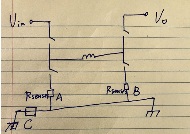
I have a 4 switch buck boost circuit, as the input/out voltage are in 200V, it is hard to find current sensing amplifier to withstand that voltage, I am thinking to put the sensing resistor at low side, in series with the low side switches, as shown in position A and B. Since both input side and output side are earth grounded, so position C is not possible.
I am wondering if you have reference designs similar to this, and if you can recommend an amplifier for it.
Also the minimum switching frequency is 400kHz, thinking push to 1MHz.
Thanks!
Hi Shengnan,
the shown connection between the cold ends of Ra and Rb, what is it? A wire? What is the distance between these two points? Can it be made zero?
I ask, because here common mode noise could develop making an instrumenation scheme necessary. If, on the other hand, both points were identical, a simple OPAmp circuit could do.
Kai
Shengnan,
I'm in agreeance with Kai here that a standard op amp may be a better design choice for such a circuit. The main reason behind this is signal integrity, as if you need the full fidelity of your inductor current, the fastest device that we can offer for dedicated current sensing is the INA293, which tops out at a ~1.2MHz BW. Just curious, with the 200V bus here, does your design need any form of isolation at any point, i.e, are you planning on feeding this signal across an isolation barrier?
Hi, Kai,
Thanks a lot for your reply.
There should be nothing at position C. I just drawing a sensing resistor ,in some cases, people put sensing resistor there, but it is not for our case, because both left and right side of position C is earth grounded.
Both Ra and Rb cold side are connected to ground plane.
Hi Shengnan,
if they are sitting so close that no common mode noise is developing between them on the ground plane, you can easily take standard OPAmps for the job and no instrumentation amplifier scheme would be necessary.
The OPAmp must be able to handle a 1MHz triangle wave without distortion, right? TI may want to recommend you a suited OPAmp
Kai
Shengnan,
Assuming you don't need isolation, I am going to loop in the high speed amplifier group to recommend a high BW op amp for the low side as we're discussing here.
Hi, Carolus,
Is there anyone from high speed amplifier group can help me on this issue?
Thanks,
Hi Shengnan,
we need some more details on your application. What supply voltages do you use? What is the input signal? What gain do you intend? What do you want to connect to the output of the OPAmp? How is the further signal processing? Is the connenction of an ADC or MCU planned? Do you need any sort of isolation later in the signal chain?
Kai
Hi, Kai,
Thank you so much for following up. Really appreciated.
1. 3.3V supply is preferred.
2. The topology is 4 switch buck boost as drawn above, the position of the sensing resistor is in position A or B(ignore position C, nothing there). The current waveform in position B look something like the red line in the attached drawing.
3. gain of 20
4. output goes into ADC input pin or CMPSS input pin of F280049 micro
5. not planning use isolation
Thank you Kai for the initial questions!
Hello Shengnan,
We have a new high speed reference design for this type of application that can be found at this link: High-Speed Low-Side Current Sense Reference Design.
Since you will need a gain of 20V/V at 1MHz, I would suggest choosing the higher end of the suggestions in the reference design: OPA2836.
Thank you,
Sima
Sorry for the late response. Regarding isolation, if sensing resistor is in high side, in series with inductor, then I have to find isolated solution, that is the reason i am thinking put it in A or B position. Since the micro controller also reference to earth ground, when sensing at A or B position, I don't need isolation , right?
Hi, Kai,
There is nothing at C position. there is an earthground layer, where code side of A and B both connect to. Will there be a lot of common mode noise with this configuration?
Hello Shengnan,
You won't have ground issues with high-side sensing. But that is correct, you will have a high common mode voltage which would mean the CMRR of the amplifier would be a significant factor in your choice of amplifier.
Below are references for high-side current sensing:
Thank you,
Sima
Hi Shengnan,
sorry for the delay.
If you can connect the signal ground of your OPAmp circuit directly to the earth sides of A and B and if A and B are very close to each to other, then you will have almost no common mode noise. The more you move away (in the truest sense of word ) from this ideal configuration, the more the common mode noise will increase. But I think the wanted signal could still be much higher then than the unwanted common mode noise. So, you could either succeed with a simple OPAmp circuit without using a differential amplifier topology or with a simple differential amplifier built by discretes as shown in Sima's link above which I repeat again below:
This scheme is ideal if you have to struggle with a bit of common mode noise and if you don't want to run the OPAmp with a bipolar supply voltage. You would connect R1 and R2 closest to the shunt. The common mode noise will develop between the connection of Rsh and R2 and the earth terminal in the above picture. Keep this line as short as ever possible, best for both amplifiers. Use a ground plane or at least a local ground plane for these connections to guarantee the lowest inductance ever achievable. And connect signal ground of your circuit close to the shunts' grounds.
Another option is to use a differential amplifier without pseudo ground and to add a small negative supply voltage, for instance by the help of LM7705.
I think, because of the high speed of your application a low side measurement is heavily recommended here over a high side measurement. Otherwise you would need to have a very high common mode rejection at 1MHz and way above, which would be hard to achieve even with the most superb amplifier. I think you can completely forget a high side measurement here.
In any case you will definitely need a solid ground plane. Don't even think about omitting it!!! You will also profit from some suited passive low pass filtering at the input of OPAmp circuit. But you will need to spend some time to find the best compromise. And you may need to split the necessary gain of 20V/V onto two OPAmp stages. The small signal bandwidth of even the fast OPA2386 is only 12MHz at a gain of 10V/V leaving not much gain reserve at the harmonics of your 1MHz triangle/square wave signal. Eventually you will need to take a faster OPAmp than the OPA2386. Happily TI has lots of them.
Kai