Part Number: OPA313
Dear TI-san,
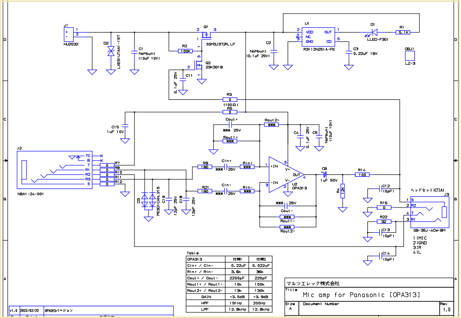
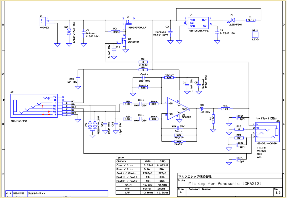
I asked about OPA313 circuit at the following URL.
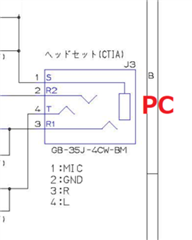
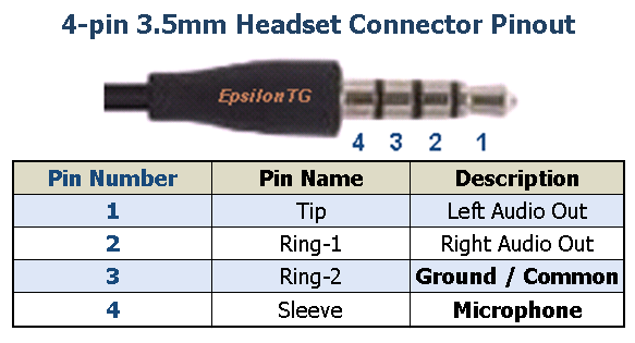
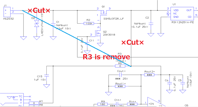
And I made a board to which the following circuit was applied.
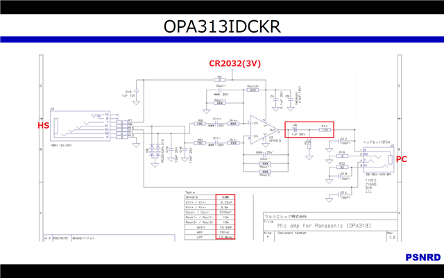
The following is an excerpt of some of QA in it.
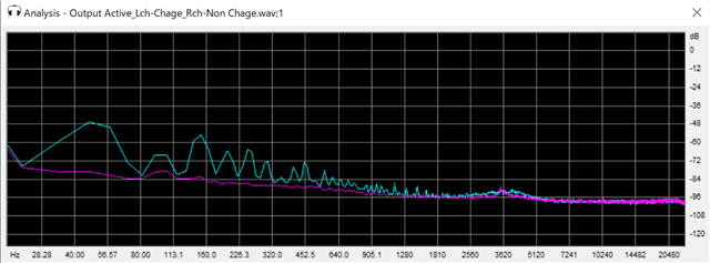
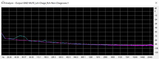
> But decrease the cap at the output from 22µF to 1µF then. The reason: 22µF can show a much worse distortion compared to 1µF.
1
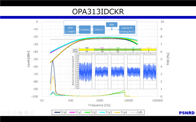
I have acquired and confirmed frequency response for your advice (THD).
The result is opposite of your advice (THD).
I want to hear your opinion.
2
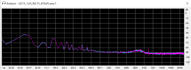
22uF and 1uF make a difference in background noise.
In particular, I am concerned about the fact that relationship between frequency characteristics and background noise is reversed.
I want to hear your opinion.
Thanks,
S.Suzuki