This thread has been locked.

If you have a related question, please click the "Ask a related question" button in the top right corner. The newly created question will be automatically linked to this question.

TLV313-Q1: output value when input higher than VCM

Part Number: TLV313-Q1
Other Parts Discussed in Thread: TLV313

Hi Expert,

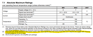
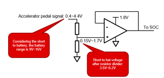
My customer is considering to use TLV313-Q1 as a buffer to isolate the short to battery voltage. You can find the block diagram as below. The normal operating input voltage of TLV313-Q1 is about 0.15V to 1.7V. But in customer's use-case, there will have short to battery case. The short to battery voltage range after resistor divider is about 3.5V to 6.2V which is higher than the TLV313-Q1 input common mode voltage. My question is that what is the output value when the short to battery performed? Is it 1.8V? 

During the short to battery situation, there is no need for output this value. But customer would like to detect the short to battery situation. If the output value is 1.8V during short to battery happens, customer would like to use 1.8V as a threshold for SOC to detect the short to battery situation. 

Do you see any other risks for this use-case? 

Thanks!

Ethan Wen

  • Hey Ethan,

    What are the values of your resistor divider?

    The TLV313 has esd diodes that clamp the input voltage to V+. The voltage at the input terminal will be one diode drop above V+, which should still be in the valid common-mode range of the device. However, the ESD diodes are not meant to conduct much current, and to avoid damaging the ESD cells should not see more than 10mA. See the absolute maximum table of the datasheet.

    Best,
    Jerry

  • Hi Jerry,

    Thanks!

    It is clear. Why you ask the resistor divider values? Are you concerned about whether the input impedance of the amplifier affects the voltage divider ratio?

    Best,

    Ethan

  • Hey Ethan,

    The reason for asking the value of the divider is that I want to know what the max current into the pin will be. If you can provide it I can better answer if the overvoltage condition will damage the device.

    Best,
    Jerry

  • Hi Jerry,

    The resistor divider values customer plan to use are 3.9K/2Kohm.

    Please let me know if have any concerns.

    Thanks!

    Ethan Wen

  • Hey Ethan,

    3.9kOhms gives a current of about 1.1mA, which should not damage the device.

    Best,
    Jerry

  • Hi Jerry,

    Thanks!

    Another question I would like to check with you.

    In datasheet of TLV313-Q1, the max output swing is 25mV/RL=2K. 

    What is the max output swing when RL=1K?

    Regards,

    Ethan

  • Hey Ethan,

    As that is not something that is specified in the datasheet so the best we can provide is an estimate from the datasheet points. First of all though, 

    In datasheet of TLV313-Q1, the max output swing is 25mV/RL=2K

    The max output swing is 100mV from rail with a RL of 2K, not 25mV.

    That being said, the swing decreases as the load resistance decreases, so you should expect max swing from rail should be greater than 100mV from rail.

    Best,
    Jerry 

  • Hi Jerry,

    What you mentioned that the max output swing is 100mV. But it is 5.5V supply voltage characteristics. 

    Customer is using 1.8V as power supply. So I assume the max output swing should be lower that 100mV, correct? There is no max output swing value under 1.8V supply in datasheet  

    Thanks!

    Ethan Wen

  • Hi Ethan,

    keep in mind that the maximum output voltage swing is the result from the OPAmp output going into saturation. Because the OPAmp is no longer working in its linear operating range when hanging in saturation, the performance of OPAmp will considerably degrade. It's no longer guaranteed then that the OPAmp is properly driving an ADC input, for instance, or is doing other things.

    You should look at the "open loop gain" specification to find out what load the OPAmp can drive before going into output saturation:

    This reads to 50mV with a load of 100k and 0.1V with a load of 10k. And with a 1k load the minimum output voltage to prevent output saturation will be even higher.

    Kai

  • Hi Kai,

    Thanks for your detailed information. 

    Do you have the data of 1k load? Customer need to know the data to define the max effective input voltage.

    Thanks in advance!

    Ethan Wen

  • Ethan,

    I think you can still use the output swing to rail in this case. Your short to battery condition will drive the device into the non-linear range. Therefore looking at the output swing to rail conditions. It should be close to 100mV from rail, degrading slightly due to the lower supply voltage. We give the measurements in the datasheet as a guideline and to establish trend.

    Since 1.7 volts is the top range of your normal operation, you can try 1.75V as the short circuit to battery detect. You can test this in a prototype to confirm, and design in headroom to allow for process variation.

    Best,
    Jerry