A related question is a question created from another question. When the related question is created, it will be automatically linked to the original question.
If you have a related question, please click the "Ask a related question" button in the top right corner. The newly created question will be automatically linked to this question.
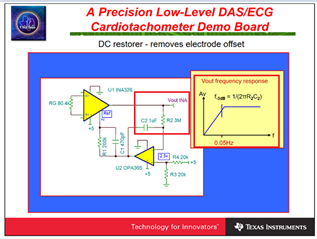
INA826: Method of removing DC component in differential mode signal
Please send us the reference design or information to remove the DC component below 0.1HZ.
You may add integrator at Vref pin as shown in the slide below, which it will act like a HPF. Before you implement this in your design, please find out where differential DC components are from. The input analog front end (AFE) is required to be balanced (better than 1%, prefer to 0.1% to 0.01%). You may require to use shielded cable to reject the common mode noise.
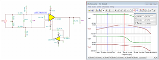
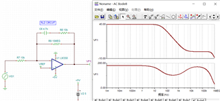
Enclosed is a simulation in INA826. I made up a condition for your reference.
The DC component has now been significantly improved.
The common mode suppression and feedback adjustment circuit have obvious effects according to the reference, but there is still a common mode output, which does not achieve the desired effect.
Please explain the matching relationship or formula of C11, R6 and R5 and other ways to improve common mode rejection.
Are you working on ECG application? It will be helpful to know your application.
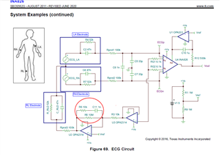
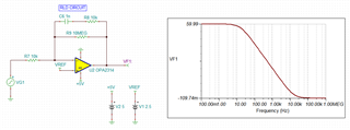
This is an integrator with Gain of 1000 V/V as shown in the simulation below or you may refer to as DC gain with a pole at 15.9Hz and zero at approx. 15.9kHz. It should invert the measured common mode signals obtained from the ECG IA, and gain it up as common mode input noise that applies it at the reference electrode or body.
I do not have good explanation why it is there. I checked with old ECG reference design, it is not there. My speculation is that it is placed there to prevent possible oscillation at electrode side for the ECG application. If the circuit is driving RLD without 100kΩ isolation resistor, then it will make sense that R8 may be there. With 100kΩ isolation resistor, I do not believe that it is needed with in the schematic, but it won't hurt either.
You should check for op amp driving stability in RLD circuit. Human body has a wide range of capacitive load for ECG application, and you should take into account of these variables.
The transfer function is: -R9/R7*(sR8C6 + 1)/(s(R9 + R8)C6+1))
Regarding to your second questions, can you send me your schematic? Did you configure Vcm range and DC bias voltage correctly?
This differential input test can cancel most of the common mode interference, but it is very difficult to completely cancel it.
When the single-ended input signal is used, no valid circuit has been found. Please recommend the circuit related to the single-ended signal.
as follows:
9.3.1.2 Analog Input for ads1299
Best,
Sunm
volume_up
32/5,000
翻译结果
However, when the single-ended input signal is used, no valid circuit has been found. Please recommend the circuit related to the single-ended signal.as follows
... but it is very difficult to completely cancel it.
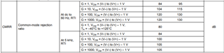
I do not have your circuit, and I am unable to comment on it. From INA826's datasheet, 120dB CMRR at Gain =100 V/V is specified.
If the CMRR is 1 V across the input of ECG signal, there is 1/10^(120/20) or 1uV/V low frequency rejection, which is typically adequate for most application. I do not have your design requirements.
In addition, if you use gel electrolyte to interface ECG electrode interfaces, which the input signals may be further enhanced from ionic to electrical signal conversion at the surface of Ag/AgCl dry electrodes.
If above approaches are not enough, you may further apply higher order LPFs to attenuate the output signal from INA826, say 50Hz or so.
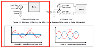
Regarding to your single ended questions, it is not clear what you are asking. The slides indicated that pseudo differential signal vs. full differential signals, where FDA has better ability to reject common mode signals. The input of INA826 is equivalent to FDA, but the output is single ended. If you prefer FDA IA, then you may consider INA851. Otherwise, you may use post higher order LPFs to further attenuate the unwanted signals.
This EEG needs to be amplified by about 2000 times before being applied to the ADC.
Small deviations are caused by the presence of very obvious common mode signals at the back end.
Before we tried the ADC, the common mode was very difficult to control below 20mV
The reason for the single-ended input is that due to the large number of input channels, the differential input requires two electrodes per channel, resulting in too many electrodes, poor contact and reduced comfort.If you have solution materials or circuits for single-ended input and common mode interference suppression, please recommend them to us.
Regardless how ECG circuit is implemented, the application circuit will require differential input signals at the ECG's analog front end. The Vcm signal over human skin surface is larger than the ECG signals, singled ended input circuit is unable to differentiate the signal.
You may build your own differential discrete input amplifiers to "lower" the cost, the total cost will end up higher, and the ECG performance will be a lot lower than the integrated instrumentation amplifiers (IAs) in the end. In our IAs, the internal resistor matching is at 100ppm or 0.01% level or better, and that are part of the key parameters to increase CMRR in the analog front end.
This EEG needs to be amplified by about 2000 times before being applied to the ADC.
We have a fixed gain INA848 amplifier, which will work well for the application. Regarding to your next questions, there are no current solutions get around the application, unless you are able to build integrated ECG electrodes that are able to transmit ECG data over wireless communication. In any case, the ECG's analog front end will be still the same, except the circuit design is integrated over a contact electrode and DAQ interfaces.
The reason for the single-ended input is that due to the large number of input channels, the differential input requires two electrodes per channel, resulting in too many electrodes, poor contact and reduced comfort.
Regarding poor contact, the electrode and skin interface may require conductive gel to enhance the contact surface. The practice will also improve the ECG signal strength at the input. I am unable to help the remaining issues, since this is the current ECG measurement technique. To improve the CMRR further, it will help if shielded cable or wire with matching input impedance are used.