Other Parts Discussed in Thread: AMC1302,
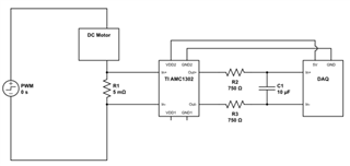
I'm using this amplifier EVM to act as a current sensor by means of a shunt resistor, with the differential output of the AMC feeding into a DAQ. I'm trying to measure the current that a DC motor is drawing, and I'm dealing with a 0-48V PWM signal.
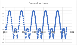
With the default setup I've been experiencing quite a bit of noise in my measurements. I tried implementing an RC filter at the input of the AMC1302 using the recommended surface mount design in section 8.2.2.2 of the datasheet, but this did not improve the noise. Since then I've tried using a separate RC differential low pass filter at the output of the AMC1302EVM. This seems to improve noise considerably. However, when the motor is in its "reverse" direction, drawing current such that INN and INP are now "switched", the data the DAQ receives is incorrect. When graphing the current measurement vs. time of the motor while it is ramping to max forward speed and then back down to max reverse speed, I get the relationship seen in the attached graph. It almost seems that the signal in the reverse direction is being rectified.
My next step in troubleshooting was to examine how the AMC is being powered. I have a 5V supply powering the low side of the EVM board, so VDD2 and GND2, and from what I understand this 5V is also being supplied to the high side through an isolated transformer, according to the AMC1302EVM datasheet.
The only thing I'm still confused about is how the GND1 pin on the AMC1302 should be connected. In the AMC1302 datasheet, it says that the GND1 pin should be shorted to INN through either a hard short or a resistive path, as described in section 8.3. Looking at Figure 6 in the AMC1302EVM datasheet, it appears this would be possible if one were to remove the C4 and C5 10pF capacitors included and short those connections to ground. Or alternatively, shorting the INN and GND1 screw terminals on the EVM board directly with a wire. I was wondering what TI recommends when it comes to this connection. Should I de-solder C4 and C5 and solder on 0 ohm resistors to short GND1 to INN, or should I connect the INN and GND1 screw terminals directly? In addition, my main problem of this signal being "rectified" under certain conditions still remains unsolved, so is there any other steps that TI would recommend I take to potentially mitigate this issue? It's worth noting this is only a problem when I add my filter at the output, as without a filter the signal is not "rectified", albeit incredibly noisy. I've tried having the filter at the input side, but this does not seem to eliminate noise at all.