Other Parts Discussed in Thread: TINA-TI
Hi TI,
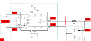
Recently I want to use one instrument amplifier because of its low RTI noise.
My requirement is output noise less than 10pA/sqrt(Hz) in DC frequency band.
I only find that the RTI voltage noise is about 1000nV/sqrt(Hz), when G = 1, in this band from INA849 datasheet.
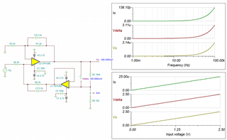
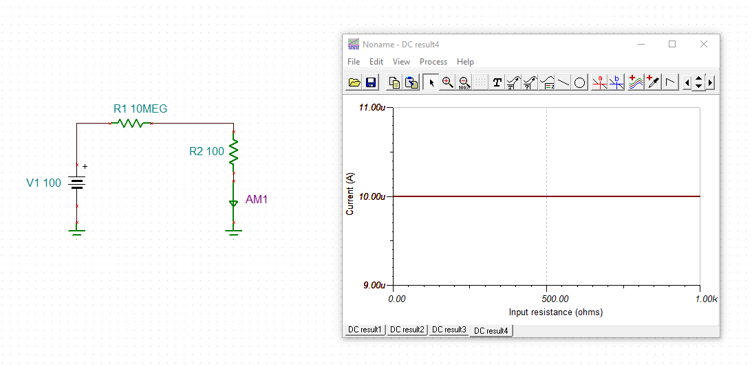
If I need use one resistor which is larger than 100kOHM to meet my requirement?
Or shall I choose one more accurate INA chip?