This thread has been locked.

If you have a related question, please click the "Ask a related question" button in the top right corner. The newly created question will be automatically linked to this question.

OPA656: Transimpedance amplifier

Genius 14779 points
Part Number: OPA656
Other Parts Discussed in Thread: OPA657, LMH6609

Hi  Experts,

Good day. Seeking your advise on this.

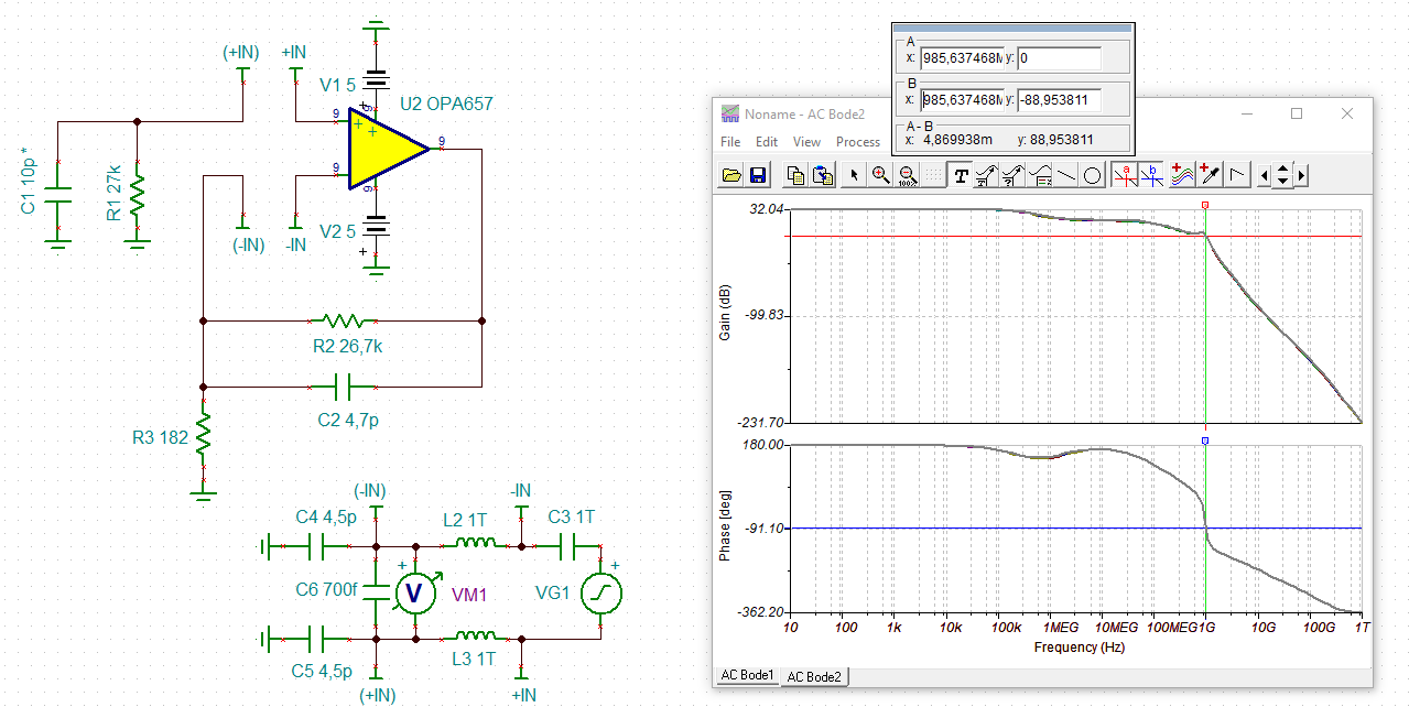
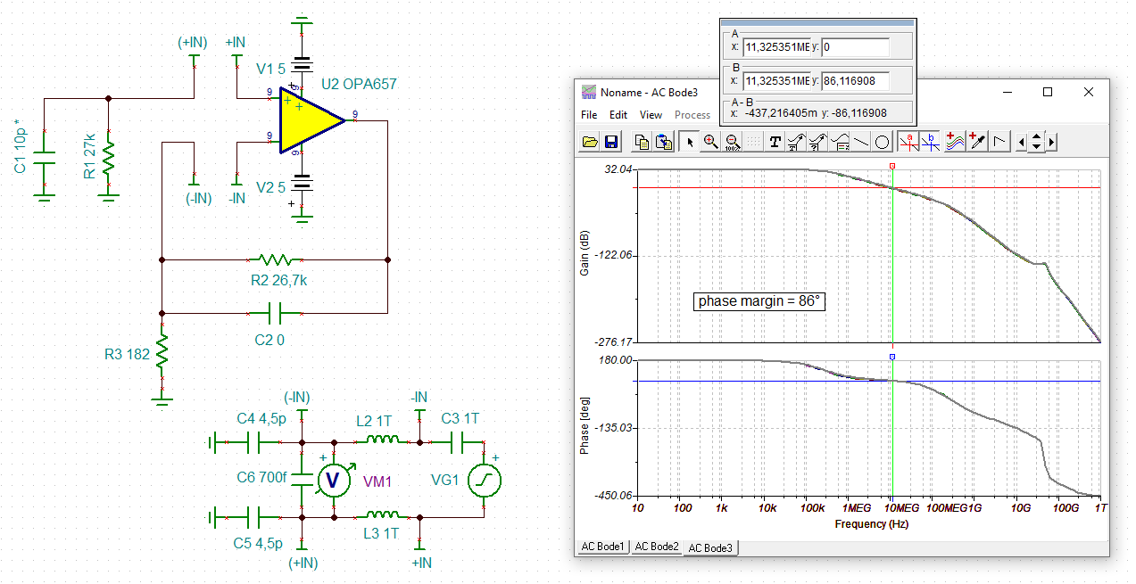
I am having problems with your OPA656 transimpedance amplifier.

I am using the amplifier as a convertor for a photodiode. The output DC value starts to change as the part starts to warm up.

This DC value comes back to 0 volts when I cool down the part. We are working at room temperature.

I simulated this design utilizing the TI simulator and it did not show this issue, so I am confused.

Thank you.

Regards,
Archie A.

  • Hi Archie,

    a schematic would be helpful.

    Kai

  • Hello Archie,

    Please share a schematic and/or simulation results so we can best assist you.

    Best,

    Alec

  • Well archie, there is both an input offset and Ib shift with temperature (not in sim model), without schematic hard to say, I would note two things, 

    1. there is a B grade with screened lower offset drift, 

    2. The Decomp OPA657 will give wider BW and a little lower noise if need be. 

  • Hi Experts,

    Thanks for waiting as I have just got the information needed.

    See attached. We are certainly under a great deal of pressure to get this product out. We would also appreciate a package equivalent of the op amp if we cannot sort this out. We initially picked the high speed amplifier to ensure the detection of short pulses. However, we may be able to lower the bandwidth of the amplifier but ideally have low bias current.

    Thank you.

    Regards,
    Archie A.

  • Additional updates:

    I have breadboarded the design with a single amplifier and measured the current consumption @ 10 mA per rail. NOTE: This is with the input on. There is no heat on the device at all. Hence my confusion as to why our production sensor board heats up. Also, if required, we can utilize a slower amplifier but the physical footprint MUST be the same. Any thoughts would be appreciated.

    Regards,
    Archie A.

  • Hi Archie,

    hhm, I'm a bit confused. The amplifier you have shown is no transimpedance amplifier (TIA) but a non-inverting amplifier?

    Kai

  • Hello Kai,

    Thanks for supporting.

    Yes, apologize. We are using the amplifier in a non-inverting configuration, as we utilize a resistor to convert the sensor current to voltage. We are following the manufacture's approach for this type of sensor.

    We selected this amplifier because of the low bias input current, high bandwidth with high gain(150).

    Thank you.

    Regards,
    Archie A.

  • Hello Archie,

    Thank you for clarifying the circuit behavior; I will investigate and check with my team on possibly causes for your heat on the production board.

    Could you share any information about the production board, whether it be board files, images, description of the thermal observations, etc?

    Best,

    Alec

  • Hi Archie,

    the circuit is instable:

    archie_opa657.TSC

    The reason for instability is that the OPA657 is an OPAmp which needs a minimum gain of 7V/V. But C2 (in my simulation) heavily decreases the gain at high frequencies and destroys the phase margin.

    Removing C2 restores the phase margin again and guarantees stability:

    Kai

  • Hi Archie,

    also keep in mind that changing from a TIA to a non-inverting amplifier has some disadvantages. You loose all the advantages of the unique TIA topology. This primarily means that the detector capacitance, stray capacitance and the input capacitance of OPAmp will form an unwanted input voltage divider. Also, the photodiode current now causes an unwanted voltage drop across the 27k input resistance and by this changes the bias voltage of photodiode. You don't have any longer a zero bias voltage at the photodiode but a bias voltage which depends on the photodiode current. This means a change of sensitiviy of photodiode depending on the photodiode current.

    Kai

  • Hello Kai/Aec,

    Thanks for sharing your insights.

    Upon removing the capacitors as you indicated, the opamp still running but in extremely hot (measured at 60 degrees C).

    Changing opamp to LMH6609, while the power consumption and heat are way down, this amplifier has a huge output offset with NO signal coming in. Both amplifiers should work with a gain of 150.

    Hoping to hear experts response.

    Thank you.

    Regards,
    Archie A.

  • Hi Archie,

    Upon removing the capacitors as you indicated, the opamp still running but in extremely hot (measured at 60 degrees C).

    When running the OPA657 as a non-inverting amplifier the OPAmp expects to see a low source impedance. But in your circuit it sees a 27k resistor in parallel with a very small detector capacitance. This can destabilize the OPA657. Keep in mind that the OPA657 is a decompensated 1.6GHz OPAmp. Such a fast racehorse cannot be treated like a slow standard OPAmp. It might not work properly in conditions it has not been designed for.

    And unwanted load capacitance at the output coming from a non-isolated scope probe can also cause stability issues. Never touch any pin of a HF-OPAmp directly with the scope probe. Insert a suited isolation resistor first. See figure 17 of datasheet. And mount this isolation resistor directly at the pin of OPAmp.

    Another cause of instability is the setup. Even only a few millimeters of copper traces at the wrong point can destabilize the OPAmp. Unsuited decoupling caps can destabilize the OPAmp. And omitting a solid ground plane can destabilize the OPAmp.

    Changing opamp to LMH6609, while the power consumption and heat are way down, this amplifier has a huge output offset with NO signal coming in.

    Yes, of course, because the LMH6609 has a typical input bias current of up to 2µA. 2µA times 27k gives a self-inflicted input offset voltage of 54mV, times a gain of 150V/V results in an output offset voltage of 8.1V!

    Do you see now that the 27k resistor at the input of a HF-OPAmp is no good idea?

    Kai

  • Hi Expert,

    Good day.

    Here is the layout. All amplifiers are routed the same way. All components are identified. NOTE: The 4.7pF cap has been removed as per your previous recommendations. No oscillations, perfect performance, just too much heat.

    Have a solid ground plane underneath these amplifiers. The loading is quite light. All amplifier components are right beside the pins that utilize said components. So assuming the layout have sorted out. All is working good except for too much heat.

    Hope you help this out.

    Thank you.

    Regards,
    Archie A.

  • Hi Archie,

    I think you can make the copper tracks wider, as shown in this layout example:

    https://e2e.ti.com/support/amplifiers-group/amplifiers/f/amplifiers-forum/924141/opa380-layout-for-signal-inputs-for-opa380

    https://e2e.ti.com/support/amplifiers-group/amplifiers/f/amplifiers-forum/1033505/opa847-in-this-tia-circuit-can-i-use-series-resistors-dividing-voltages-to-couple--vbias-to-the-pin-s-anode-when-the-dc-voltage-source-is--5v-and-the-anode-voltage-needs-to-be-1v

    This will enhance the heat dissipation.

    Oops, are you using through hole components? Even for the supply voltage decoupling caps? Not good... way too much inductance.

    Kai

  • Hi Alec/Kai,

    The ground plane is solid, and the power supply traces are about .025 wide. All signal traces are between .007 and .013. Could you elaborate what particular part from layout need to adjust? Sorry if the this query has overwhelmed follow ups.

    Also, all components are surface mount with said components very close to the input pins. We have seen no oscillations in the lab, so I am not sure why these amps run so hot.

    Thank you..

    Regards,
    Archie A.

  • Hi Archie,

    We have seen no oscillations in the lab, so I am not sure why these amps run so hot.

    Ok, what is the supply current consumption of the OPA657 getting hot? Is the supply current relevantly increased at all, indicating an usual operating condition?

    If the supply current is not relevantly increased, then you have a heat dissipation problem. In this case increase the width of copper tracks as I already mentioned. Keep in mind that vias are no good heat conductors at all. So the OPA657 will not profit from the wide copper tracks running to the VCC and VSS pins.

    It's very well possible that your breadboard design coould dissipate the heat much better than your printed circuit board design.

    If the supply current is increased, on the other hand, I would carry out some very simple tests to find the cause of heating :

    1. Disconnect any load from the output of OPA657 (the feedback components excluded, of course). Is the OPA657 still getting hot?

    2. While having everything disconnected from the output of OPA657, disconnect any other OPAmp and other circuitry from the common supply voltages, as if only the OPA657 was mounted on the board. Is the OPA657 still getting hot?

    3. Additionally disconnect the photodiode from the input. Is the OPA657 still getting hot?

    4. With the photodiode disconnected from the input, short circuit the +input of OP657 to signal ground directly at the OPAmp. Is the OPA657 still getting hot?

    5. Add a small resistor of about 4R7...22R in series to each supply voltage line closest to the OPAmp so that this resistor together with the decoupling cap forms a RC low pass filter. Is the OPA657 still getting hot?

    .

    .

    .

    and so on...

    Play with the circuit and change everything you can change until you find the cause of heating. Keep in mind that even only a very little change of a circuit can decide between success and failure when it comes to HF circuits. And what worked on your breadboard design need no longer to work on your printed circuit board and vice versa.

    Keep in mind that a situation can occur where only the input stage of OPAmp oscillates and that this input stage oscillation can hardly be seen at the output of OPAmp. Input stage oscillations can only be detected by the increase of supply current and increased heat dissipation of OPAmp.

    Critical impedances seen by the OPAmp from the +input to signal ground can trigger these oscillations. I already mentioned that the OPA657 sees a rather unusual input impedance in your application. A small resistance in series to the +input can stop the input stage oscillation by dampening unwanted LC resonances and/or by adding some low pass filtering in combination with the input capacitance of OPAmp.

    Divide and conquer!

    Kai