A related question is a question created from another question. When the related question is created, it will be automatically linked to the original question.
If you have a related question, please click the "Ask a related question" button in the top right corner. The newly created question will be automatically linked to this question.
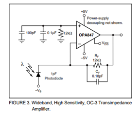
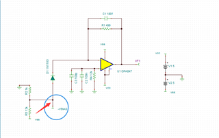
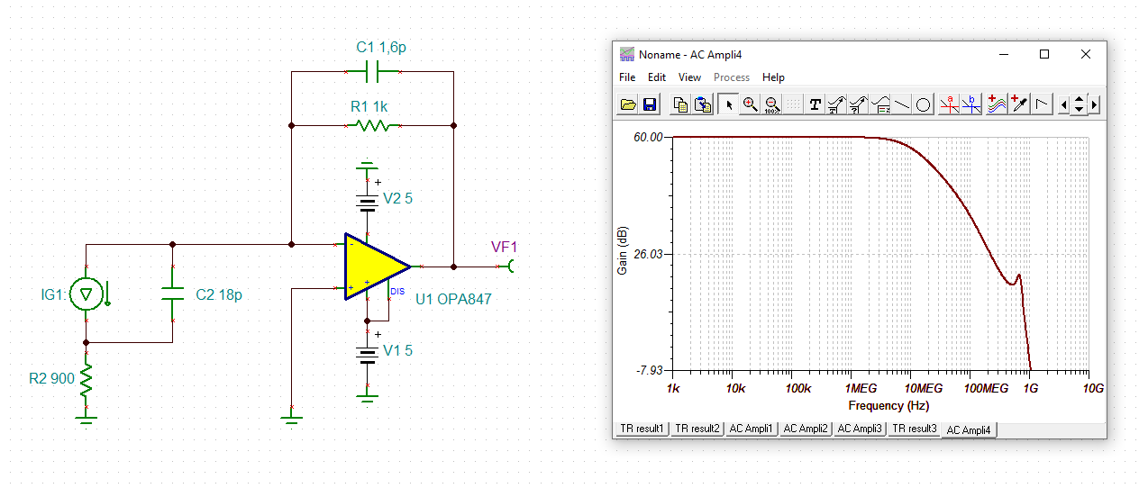
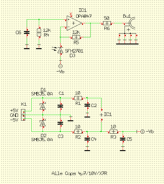
OPA847: in this tia circuit, can i use series resistors dividing voltages to couple -vbias to the pin's anode when the dc voltage source is -5V and the anode voltage needs to be-1V.
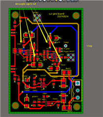
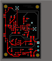
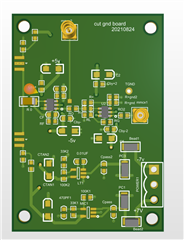
The resistors for the voltage bias should not affect the circuit, but changing the input source capacitor will affect the stability of the system. Would you be able to provide scope/measurement shots and a snippet of the pcb board layout?
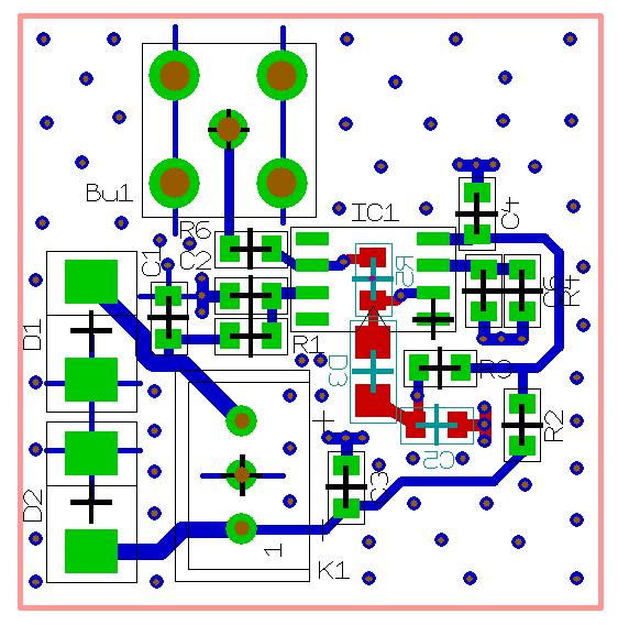
yes, I remember. I recommended to heavily reduce the lengths of signal copper traces at the -input of OPAmp. Have you modified the layout in the meantime?
It is shorter than before, but it is still pretty long. We would recommend moving the photodiodes as close as possible to that R0 component, but it is also good you moved this R0 closer to the other components as well from the previous revision. But, what is the value of the R0, and why not connect the photodiode directly and as close to the inputs of the amplifier as possible?
Are you having stability/oscillation issues on the actual circuit with this new board which is why it is not matching the Tina's simulation result?
thanks,sima R0 is a 0 value resistor,to avoid the trace's routing acute angle or right angle.
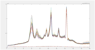
there is no oscillation,but the fft of the output is strange,i.e.
the below part of this figure is showing with no connect of this board'output to oscillascope, the top part of this figure is showing with the tia's output connect to the oscillascope.
Thank you for sharing the measurements. What is the frequency of the pulse signal into the input of the amplifier? Looks like there are additional harmonics, and usually if amplifier is oscillating there will be peaks in very high end of the frequency spectrum. Seems to be a lot of noise and distortion as well. What are the units on the x-axis of the FFT?
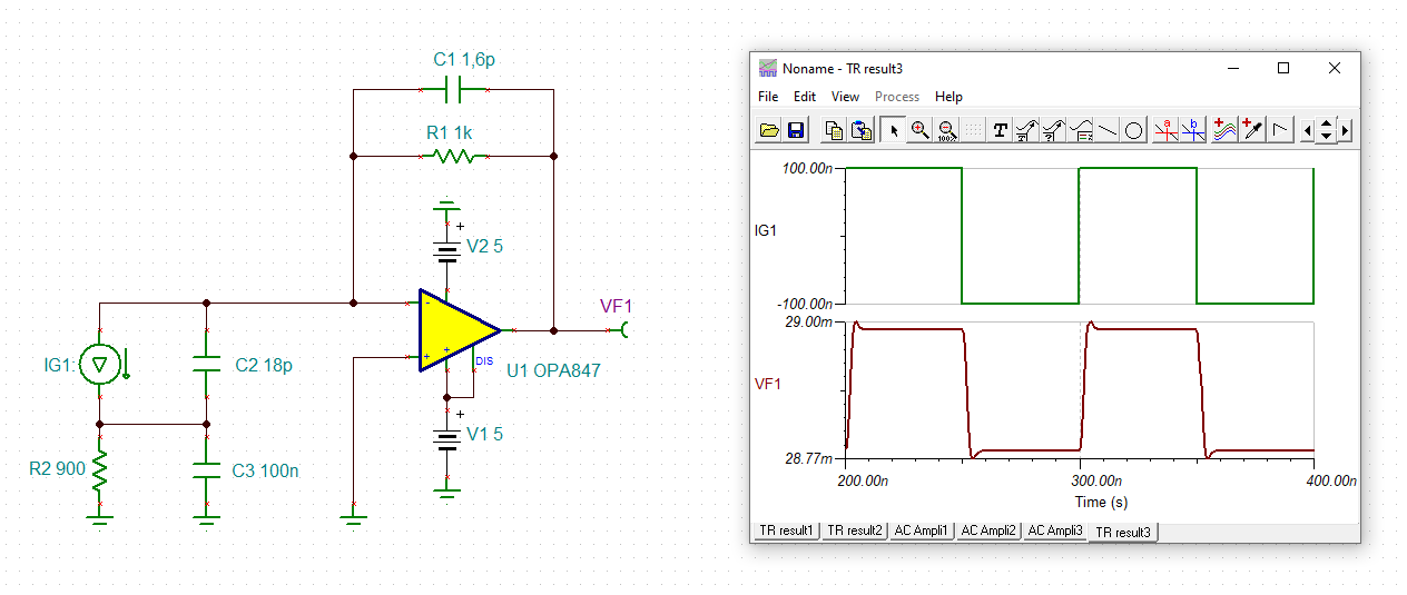
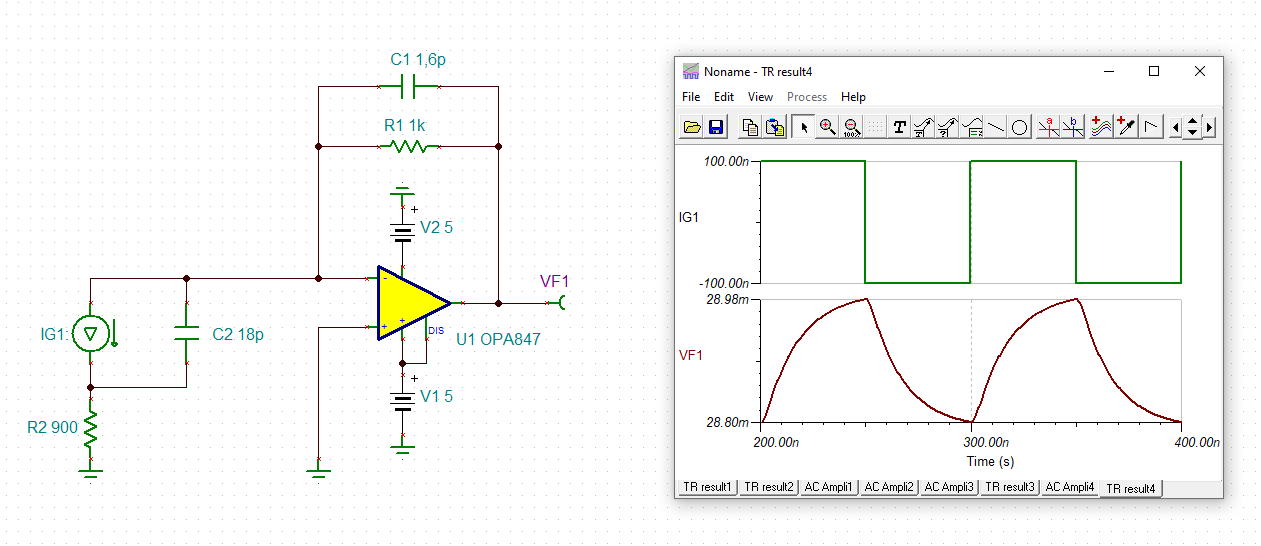
Would you be able to take a transient scope measurement as well?
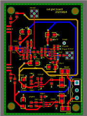
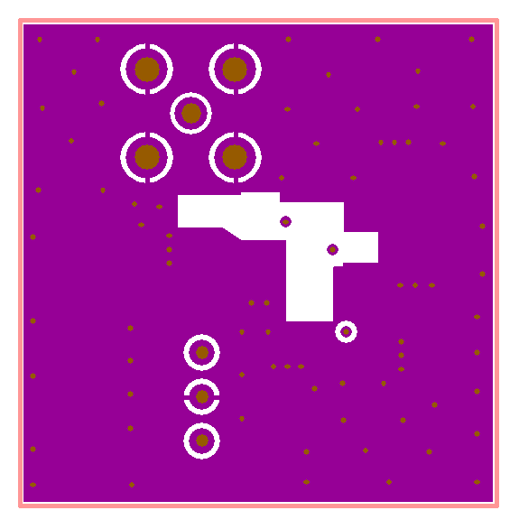
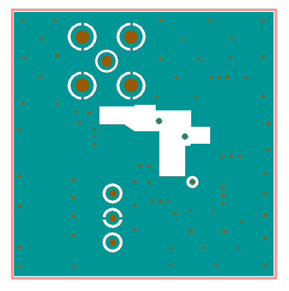
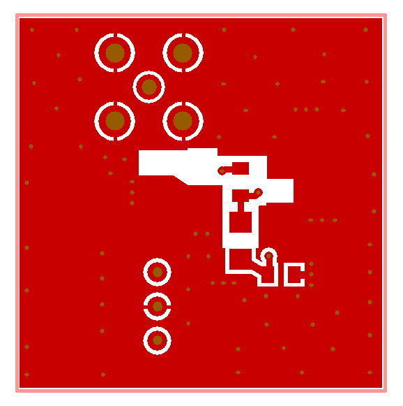
I'm sorry to tell you that your layout is not optimum.
When you start drawing a layout, first put the decoupling caps directly (!) to the OPAmp. They are the very most important components in such a circuit. Unfortunately, in your layout they are sitting way too far away from the OPAmp.
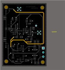
Use Pi-filters in the supply lines, when several OPAmps are powered by the same supply voltage. Simple decoupling caps will not do the trick, unless your layout is otherwise perfect (-> solid ground plane).
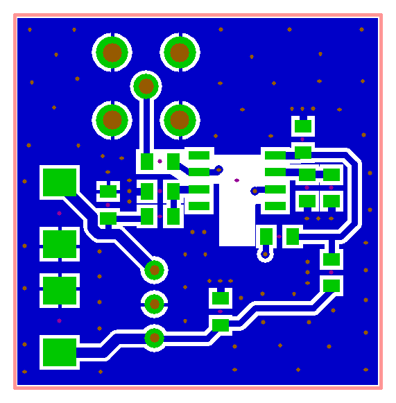
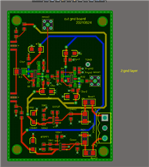
Draw a solid ground plane, but introduce gaps into the solid ground plane where the feedback components of OPAmp are sitting above.
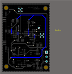
Reduce any copper trace length to the absolute minimum. Every single millimeter counts! Believe me, this is no joke. Every millimeter copper trace indtroduces an inductance of 1nH -as a rule of thumb- and can totally ruin the performance of your 3.9GHz OPAmp circuit. 10mm copper track equals 10nH and gives an impedance of 245R plus an insane phase shift.
See this example layout and compare it with your layout:
Thanks for sharing detailed PCB documents, can you also share the schematic of this board. Want to take a closer look at current values on both stages and the power on the lower part of the board. Also, I would suggest testing at each stage, would you be able to probe at the output resistor of the first stage?