This thread has been locked.

If you have a related question, please click the "Ask a related question" button in the top right corner. The newly created question will be automatically linked to this question.

AMC1311: AMC1311BQDWVRQ1

Part Number: AMC1311
Other Parts Discussed in Thread: TIDA-01541, , OPA211

Dear all,

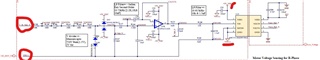
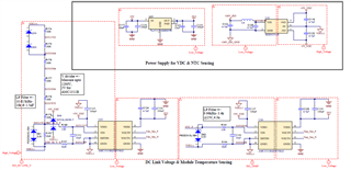
I am using AMC1311B isolation amplifier for DC link voltage sensing in motor drive application. At No load to motor, DC link measurement is linear to actual values. However with load, Measured value (at AMC output) is showing negative drift wrt actual value. We are referring TIDA-01541. Below is the section of schematic used,

Please provide clarification for the following:

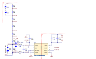
1.) What is the correct way of putting input filter components for single ended voltage measurements- either 12R+10nF+12R or 12R+10nF+0R

2.) How to connect SHTDN pin- either shorting it directly to VDC(-) or connecting it before lower side filter resistor.

3.) How Zener diode is used to detect under voltage.

  • Hi Himanshu,

    oh yes, referring the AMC1311 there seem to be some typos in the appnote. In any case, it's the datasheet you should trust and not any appnote.

    Kai

  • Hi Himanshu,

    What is the voltage range you are trying to measure? Can you please provide a table with some example values that show this "negative drift"?

    1. The resistance from the resistor divider will contribute to the cutoff frequency of the RC filter. No resistor should be necessary and a smaller capacitor can be used such as 0R + 10pF + 0R. 

    2. How SHTDN is connected is fine as connecting directly to GND1 is recommended. Connecting GND1 to VDC- is recommended. 

    3. I would remove these zener diodes as they may be contributing to inaccuracies in the measurement. The inputs of the device have internal ESD diodes that can handle up to -6V if limited to 10mA or less. 

  • Thanks for your reply,

    Our measuring voltage range is 0-1200V.

    Here is the observation for actual and measured DC link voltage with varying motor load.

    Motor load (%) Measured  DC link voltage (V) Calculated VDC based on voltage division (V) Measured VDC at AMC output(V) % error
    No-load 576 0.96 0.976 -1.66667
    40% 558 0.93 0.902 3.010753
    75% 549 0.915 0.844 7.759563
    100% 550 0.9167 0.841 8.254545

    Please note that these readings were taken after removing Zener diodes.

  • Hi Himanshu,

    I would remove all "diodes" (D59, D60, D61 and D68) and measure again. It could be that one of the diodes became damaged and shows increased leakage current.

    If the result (with removed diodes) is still unsatisfying, I would check with a fresh AMC1311 again.

    Another cause for the errors can be a heavy ripple superimposed to the DC voltage, which is measured differently by the voltmeter and the AMC1311. Remember that you have installed C131 which would filter-out the HF ripple for the AMC1311 but not for the voltmeter you connect to the VDC(+) terminal. This could have an impact of the voltmeter reading. So you should also measure directly at the input of AMC1311 and not only at the output of AMC1311.

    Applying a true DC voltage at the VDC(+) terminal coming from a DC voltage generator would also be helpful to prevent the motor's HF ripple from degrading the measurement.

    Kai

  • Hi Himanshu,

    Thank you for providing measured values. There is indeed an issue in the measurement. 

    I agree with Kai's suggestions for further debug. Measuring directly at the inputs and outputs of the AMC1311 would help identify if it's a device issue or a system issue. The system issue may either be leakage from the diodes or ripple.

  • Hi Kai,

    AMC sensed output shows the same non-linear behavior after removing all the diodes (D59, D60, D61, D68). The same observation is seen after using a newly ordered AMC1311 IC from TI. 

    The DC link ripple voltage is observed to 3% of no-load DC link voltage(565V) @ 75% load. 

    Below are some more observations during the test:

    1) When the 3-PH power supply is OFF and the power supply to AMC1311 primary and secondary are removed, the AMC output is read to be -120mV.

    The value is measured using a high-voltage probe with corrected offset and also with a multimeter with both showing the same value.

    2) When the pulses to the inverter section of VFD are blocked, the AMC output voltage (930mV) matches with the measured value exactly without any offset.

    3) When the motor is loaded, the above-mentioned non-linear behavior is observed. With the increase in load, the drift in voltage is predominant.

    Note: The power supply to AMC1311 primary {+5V_VDC and VDC(-)} is shared by other AMC 1311 ICs in the motor voltage sensing section. How the common grounding of all the AMC can affect the IC behavior? Is it advisable to isolate the grounds of motor voltage sensing and DC link voltage?

    Attaching the portion of the motor voltage sensing.

    Appreciate your valuable feedback to help us solve the prevailing issue with DC link voltage measurement.

    Thanks,

    Himanshu

    Srijeeth

  • Hi Himanshu,

    1) What are you measuring with respect to? The output voltage should be 0V since the device is not powered. What else is connected to the output? 

    3) If the signals are referred to the same ground and the common-mode input specifications are not violated, then multiple AMC's can share the same power supply. 

    Can you provide a larger block diagram of your system? 

  • Hi Alexander,

    1) Output is taken across VOUTP and VOUTN in the AMC secondary. AMC is verified to have a common mode output voltage of 1.42V when DC link voltage is not available and when the power supply to primary and secondary are both supplied.

    Are you mentioning the CMTI parameter (Under 7.9 Electrical Characteristics in the datasheet)? Could you please provide more details about how to verify the parameter violation?

  • Hi Himanshu,

    Apologies, the common-mode input specification is not applicable for the AMC1311 since it is a single-ended input device, not differential. 

    Can you share a larger schematic? There must be an alternate path for the current to travel that we are not seeing. 

  • Thanks for your reply Alexander,

    Attaching the power supply section for {Primary: +5V_VDC and VDC(-)} and {Secondary: 3V3 and GND}.

    Both +24V_ISO and +5V are isolated power supplies generated by SMPS. From 24V_ISO, the +5V_VDC is generated using the SMPS module (PEM1-S24-S5-S). 

    We shall provide an update by analyzing the noise levels and ripple voltage in both the isolated power supply. 

    We appreciate your involvement in rectifying the issue. 

    Himanshu,

    Srijeeth 

  • Hi Himanshu,

    The power supply generation circuits look OK. Have you removed all of the input diodes or only the diodes on one of the AMC1311 circuits? 

    I recommend to continue depopulating diodes and other components that are non-essential for debug while tracing the voltages through the signal chain with a DMM to try and isolate where the offset is coming from. 

    Ensuring that the resistors in the voltage divider are correct values may help as well. 

  • Hi Alexander,

    Yes, all the diodes are removed for testing and the issue still persists. We have verified the resistor values and soldered them properly. 

    The no-load readings are matching with the measurement which confirms the value of resistors used. 

  • Hi,

    Im a bit confused now. There are two circuits, one with the OPA211 and another without the OPA211?

    In the following I refer to the original schematic in your first post.

    My tipp is: Divide and conquer!

    1. Remove everything from the shown circuit. Don't connect anything to the output of AMC1311. Disconnect the 3.3V low sied supply voltage and apply the 3.3V from a lab power supply. The 3.3V must be clean, stable and noise-free. Don't use any DC/DC switcher but provide a linearily regulated 3.3V.

    2. Then, do exactly the same with the +5V high side supply voltage. Disconnect the 5V high side supply voltage and apply the 5V from a lab power supply. The 5V must be clean, stable and noise-free. Don't use a DC/DC switcher but provide a linearily regulated 5V.

    3. Remove all the diodes D59, D60, D61 and D68.

    4. Apply a clean, stable and noise-free DC voltage to the pins VDC(+) and VDC(-): This voltage must come from a lab power supply. Don't use any DC/DC switcher but provide a linearily regulated voltage.

    5. Connect a DVM to the input and a DVM to the output of AMC1311 (via isolation resistors) and determine the gain for varying DC voltages between the VDC(+) and VDC(-) pins. Confirm that no other circuitry is connected to the AMC1311 and its circuitry needed in this test during the test.

    Please report what you are seeing now. There should not be any gain error.

    If these steps were successfull, go back to the original circuit in steps, but do only go one step at a time. Do not change more than one thing at a time. Add the diodes again, for instance. Or add the original 5V high side supply voltage, for instance. Or add the 3.3V low side supply voltage for instance. Or add the circuit folowing to the output of AMC1311, for instance. But only make small steps. Do not change too many things at a time. Changing one thing at a time gives two possible results, go or no go. Changing two things at a time results in four cases. Changing ten things at a time results in 100 cases and you will never find out what's the cause of failure.

    So, divide and conquer!

    Kai

  • Hi Kai,

    Please note that the circuit with OPA211 is used for motor voltage sensing and the other circuit without OPA211 is used for DC link voltage sensing. Both the circuits were shared to understand from your reply if the common ground of VDC(-) by any means affects the non-linear behavior of DC voltage sensing.

    We have tested the PS on the primary side of the AMC1311 and found it to have negligible ripple voltage. 

    We are in the process of testing as per suggestion one step at a time. Please allow us some time to reply.

  • Hi Himanshu,

    I understand.

    Good luck Relaxed

    Kai

  • Hello team TI,

    To summarize: The issue was, that the AMC1311 output voltage would drift away from the actual measured DC link voltage.

    We have taken the observation by tapping the DC link to a new PCB (standby PCB) where only the DC link sensing components are populated (excluding all the diodes in the schematic). The AMC in standby PCB is provided with lab power supplies for both the input and output sides.

    It is observed that the original PCB (main PCB) with the AMC showed non-linear behavior whereas the standby PCB readings were accurate with the true DC link value. 

    Please share your thoughts about the behavior observed and how it can be corrected in the hardware. 

    Is it something to be corrected in the layout?

    Regards,

    Srijeeth, Himanshu

  • Hi Himanshu,

    Have you tried replacing the AMC1311 in the original PCB and re-testing? 

    If the only difference between the two boards are the diodes, then I don't see how changing the layout would offer any benefit if removing the diodes fixes the issue.