This thread has been locked.

If you have a related question, please click the "Ask a related question" button in the top right corner. The newly created question will be automatically linked to this question.

INA181: Unstable problem after using INA181A1 to replace INA214

Part Number: INA181
Other Parts Discussed in Thread: INA214,

Hi,

My customer is using INA181A1 to replace the INA214 in order to get a fast response with a higher bandwidth. Bur they found out that the output is extremely unstable regarding the interference, sometimes it may turn out to be a square wave on output. The sampling voltage over the shunt is about 10mV, and it is used to sense the current of a switching power supply topology.

So I would like to ask:

1.Are there any special requirements for interference of sampling current of INA181A1, is it suitable for using in switching power supply topology?

2.Are there any solutions for balance the response speed and the stable of system in this case with using INA181A1?

Thanks.

Regards,

Manu Chang

  • Hi Manu,

    the INA181A1 is very much faster than the INA214: 350kHz bandwidth compared to 30kHz. So it's very well possible that it behaves very differently. But this does not necessarily mean that it is "extremely unstable regarding interference". It just shows more harmonics of the input signal, which the slower INA214 is not able to reproduce. The output signal of INA214 may look smoother and less noisy, but in the end it's only the effect of its very limited bandwidth.  

    For a better analysis a schematic would be helpful and some scope plots.

    Kai

  • Hey Manu,

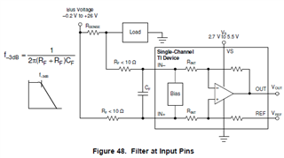
    Would you please share a schematic? As Kai mentioned the INA181 may just be picking up more high frequency current ringing. Thus, if you want the signal to be smoother, you will need to employ input and/or output RC filters. I would first start with a differential input filter of 10-Ω (RF) for each input pin and the maximum possible differential input capacitor (CF) between IN+ and IN-. The max CF allowed would be dependent upon the system's minimum required signal BW. 

    Sincerely,

    Peter