This thread has been locked.

If you have a related question, please click the "Ask a related question" button in the top right corner. The newly created question will be automatically linked to this question.

DEM-BUF-SO-1A: Attenuated output

Part Number: DEM-BUF-SO-1A

Hi Team,

A customer has this board but they are having 10x attenuated output and not unity gain.

The board was assembled as per the schematic with the corresponding value:

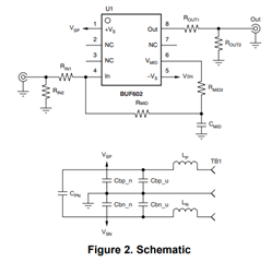
Rin1 = 50 ohms; Rin2 = 25 ohms; Rout 1= 50 ohms; Rout2= 25 ohms; Cbpu and Cbnu = 4.7uF; Cpn= 10nF; Cbpn, Cbpp= 0.1uF.

Rmid and Cmid were not connected; The Lp and Ln were replaced by 0ohm.

The board is supplied by dual voltage +/-5V

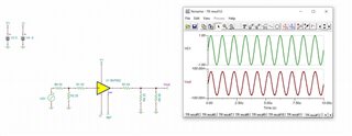
When the customer applies sine wave signal 1v peak to peak, the output they are getting is 100mV peak to peak.

Can you help?

Thanks in advance.

Regards,

Marvin

  • Hello Marvin,

      With those component values, the customer is obtaining the correct value. Rin1, Rin2, Rout1, and Rout2 act as two separate voltage dividers. 


      Above, I am assuming the customer has a 50 ohm source (R6) and a 50 ohm scope (R5). If this amplifier is designed on a custom board within an overall system, the 50 ohm impedance matching would not be necessary only if the previous and post stages are within trace millimeters to input and output node of the buffer. Otherwise, 1GHz frequency range would require impedance matching to mitigate signal reflections.  

    Thank you,
    Sima