This thread has been locked.

If you have a related question, please click the "Ask a related question" button in the top right corner. The newly created question will be automatically linked to this question.

LM2904B-Q1: Ibias vs Vcm Relation

Part Number: LM2904B-Q1
Other Parts Discussed in Thread: LM2904, TLV9004

Hello GPAMP team,

I got one question from the customer about input bias current.
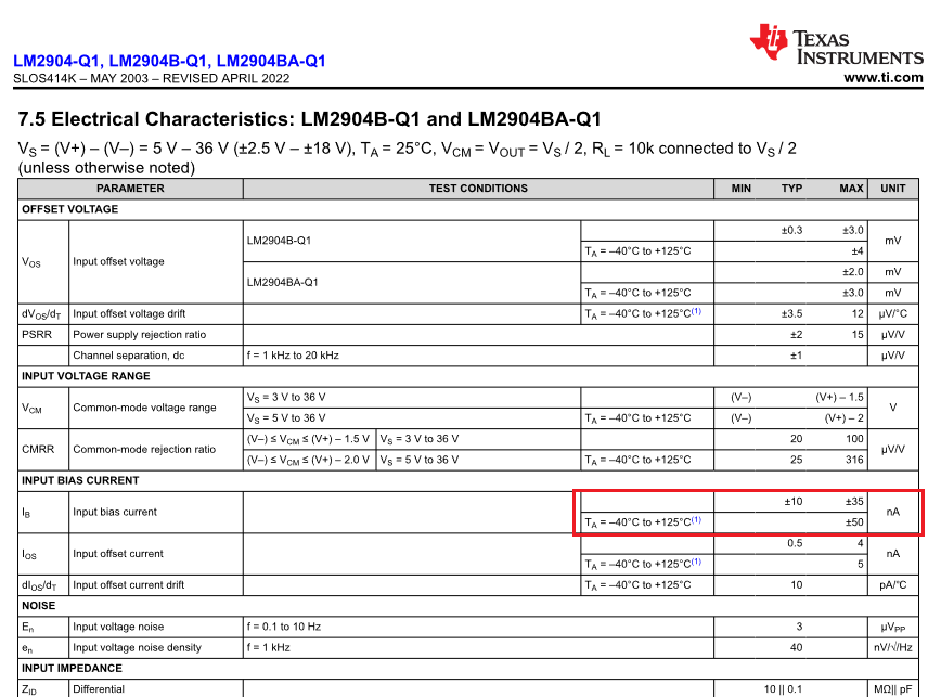
In the datasheet shows the typical performance of Ib with pointed condition. (Vs=±18V)

・Even though sweeping Vcm from -18V to +18V, the input bias currnent is same direction (pull-out from IC). Is that correct??
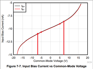
・If we need the same input bias currnent but Vcm from -7V to +7V (and Vcm is from -5V to +5V), I suppose like below.

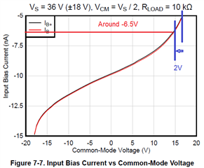
★With above condition, the voltage difference is 7V - 5V = 2V
 So that we can read the bias current (2V down from +18V) from graph curve, is that correct?

Regards,
Toshihisa Ishii in TIJ/East Auto

  • As shown in the functional block diagrams, the inputs are bases of PNP transistors. So the input current is always negative. (For details, see the Design Guidelines for Devices with LM324/LM358 Cores.)

    The input bias current depends mostly on the voltage to the positive supply. However, the voltage shown is typical, not guaranteed; if you want the values for a supply smaller than 36 V, you should measure the actual device.

  • Hi Tosh+,

    what you see in this diagram is only the typical input bias current. Keep in mind that according to section 7.5 of datasheet the input bias current widely varies. See the difference between the specified typical and maximum values:

    By the way, the +/- signs in the red box is a typo. As Clemens already mentioned the input bias current is always flowing out of the LM2904 because of the PNP transistors in the input stage, see section 9.2.

    If the input current makes trouble in your application, just take a CMOS OPAmp like the TLV9004, e.g.. Its input bias currents are way smaller compared to the LM2904.

    Kai

  • Hi all,

    Yes, the Ib chara in the graph is typical, and guaranteed values are listed in the datasheet.

    Whereas, I want BU to check my understanding is reasonable when Vs range is narrow down to 7V.

    ti

  • Toshihisa-san,

    The common mode voltage ranges you listed are centered around zero, so you should look at the common mode range from -7V to 7V on the x axis and -5V to 5V on the x axis as shown below. I drew lines for 7V but did not for 5V as there are already lines present. Additionally I need to note that this is the data of a single unit and not a representative sample of the input bias current spec.

    Best,
    Jerry