This thread has been locked.

If you have a related question, please click the "Ask a related question" button in the top right corner. The newly created question will be automatically linked to this question.

OPA564: OPA564

Part Number: OPA564
Other Parts Discussed in Thread: TINA-TI

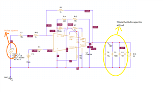
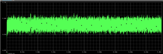
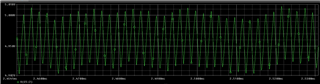
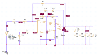
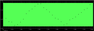
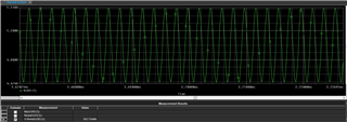
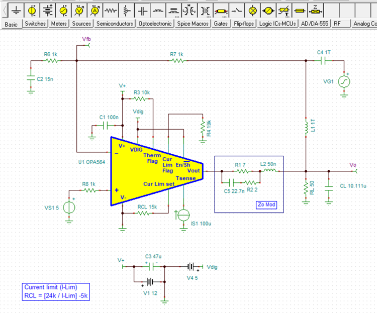
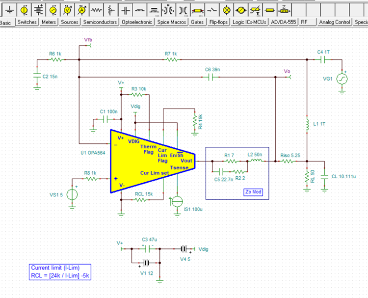
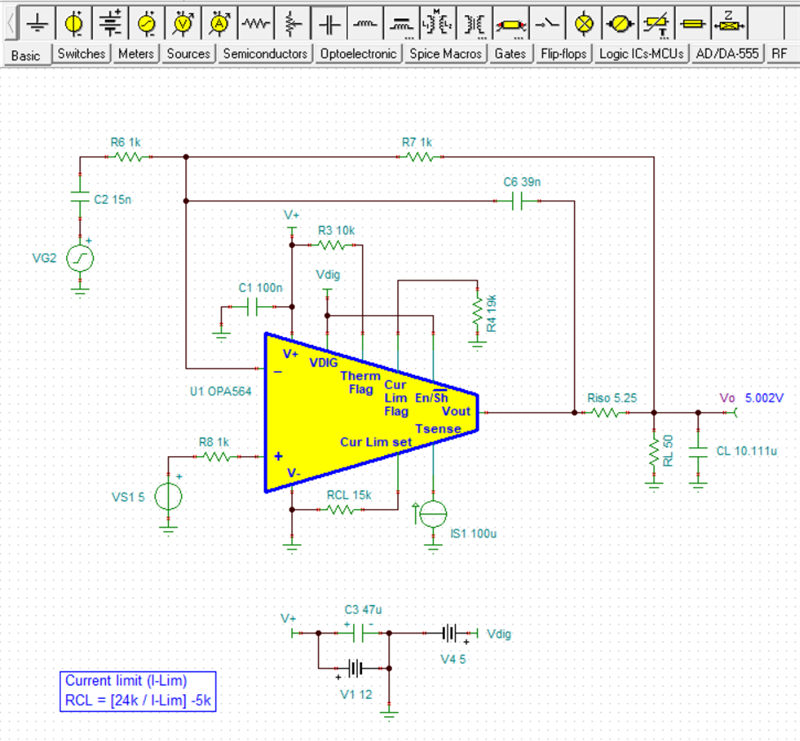
I am using OPA564 as inverting summing amplifier with unity gain. We have three inputs like noise), spike and glitch sources at inverting terminal and we have an voltage source 5V at non inverting for providing the offset. My load has large capacitor of 10u, 100n,10n & 1n and load current of around 150ma. In Most cases only one of the inverting input is provided to the Opamp so while I was providing noise input 500KHZ at 0.5Vpp I can only see very small amplitude swing at 5V offset. Also when I provide 50KHZ at 0.5Vpp I can see the noise for some time and then Opamp output goes down to 0 and again switch back to noise amplitude. But it works fine when we are providing the input noise only with load and without the large capacitors.

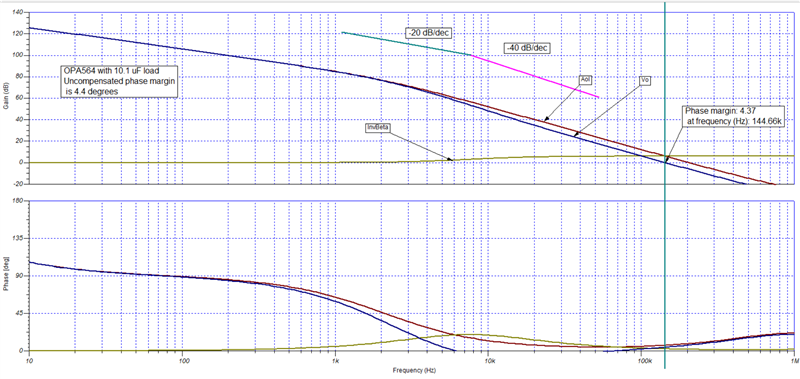
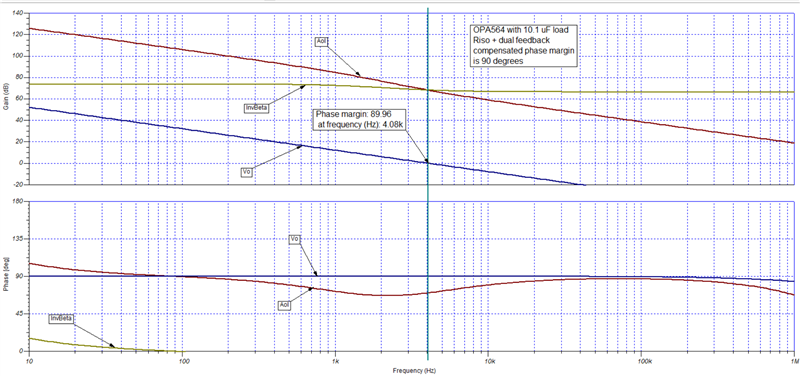
is this because the Opamp goes to instability due to the large capacitor or some other issue

  • Hi,

    a 10µF cap gives an impedance of 0.03 Ohm at 500kHz. So you short-circuit the output of OPAmp.

    Also, a 10µ cap at the output of OPAmp can destabilize the OPAmp by ruining the phase margin and can cause instability, finally resulting in oscillation.

    You could try to add an isolation resistor between the output of OPAmp and the 10µ load capacitance. Another remedy can be the use of the dual feeback method. Watch this whole video series on stability, especially video "10.6 Isolation resistor":

    https://training.ti.com/node/1138805

    Can you show a schematic?

    Also, why do you have this huge load capacitance at the output of OPAmp?

    Kai

  • Hi Lakshmanan,

    We really need to see the schematic for your OPA564 application circuit. It needs to include the power supply levels being applied to the OPA564, and show exactly how the input generator and output loads are connected. And please clarify what you mean by "Most cases only one of the inverting input is provided to the Opamp . . .?"

    How does the amplifier circuit behave when you apply an appropriate sine wave input?

    Regards, Thomas

    Precision Amplifiers Applications Engineering

  • Hi,

    thanks for the response.

    Below is the schematics.

    the response waveform is below

    Zoomed one

    when i isolate the 10u bulk with series resistor of 1ohm; i think it is coming into stable mode as it is directly not seeing the bulk capacitor.

    the output waveform is shown below. it is as expected

    zoomed waveform

    But in our unit we cannot implement this solution as we dont have the control to add series resistor to that load capacitor. please have a look and suggest the options

    Thanks & Regards

    Lakshmanan. B

  • Hi Kai,

    i have replied with schematics and observation. please have a look into it 

    Also, why do you have this huge load capacitance at the output of OPAmp?

    we are giving this output as power supply to our controller. we are basically using this as kind of noise coupler.

    Thanks & regards

    Lakshmanan. B

  • Hi Thomas,

    i have replied with schematics and observation. please have a look into it;

    Thanks & regards

    Lakshmanan. B

  • Hello Lakshmanan,

    The OPA564, like most all op amps will oscillate with a very high capacitance load and it is evident from the images you provide it is oscillating. The OPA564 datasheet in Figure 6 shows that the maximum C-load should be kept to about 40 nF when operated in a gain of -1 V/V. Certainly 10+ uF is much higher than that and external compensation must be applied if the op amp is to remain stable. Stabilizing the op amp for a high C-load can be accomplished, but the amplifier circuit bandwidth will be much reduced.

    It appears you are concerned about the op amp output level if an Riso is added in series with the OPA564 output to its load. There is a variation on the Riso compensation method we refer to as "Riso + dual feedback" that adjusts for the correct output level at the output load point. Since it appears that the output level is near the mid range of the supply there is enough OPA564 output voltage range for it to remain within the linear output region. If for some reason there isn't sufficient swing range remaining, then a compensation method external to the feedback loop would have to be explored.

    When I run a stability analysis on your original circuit using the TINA-TI simulation tool I find that the phase margin is around 4 degrees. That is too low to assure stability and that is why the circuit is oscillating with the 10.1 uF load on the OPA564 output. Here is the test circuit and gain/phase vs. frequency plot (Bode plot):

    To apply the Rios + dual feedback compensation the approximate frequency where the second order break (-40 dB) in Vo is required be determined. It appears by inspection to be occurring at about 3 kHz. That is where a zero need to be inserted in the response to bring the roll-off back to -20 dB/dec. Then, Riso is determined from:

    Riso = 1/ (2 x pi x fzero x C-load) = 1 (6.28 x 3e3 x 10.1 e-6) = 5.25 Ohms

    The feedback capacitor was determined from:

    Cf = (7.5 x Riso x C-load) / Rf = (7.5 x 5.25 x 10.1e-6) / 1e3 = 39.7 nF

    The resulting TINA-TI test circuit and resulting Bode plot are shown here:

    Note that the phase margin has increased from 4 degrees  to 90 degrees, but note that circuit's bandwidth had dropped to about 4 kHz. The circuit is now completely stable with the very high 10.1 uF C-load.

    The final circuit is shown below and the components added to do the stability analysis have been removed. A DC analysis has been performed to show that the output voltage at the 500 Ohm + 10.1 uF load is at the correct 5.00 V level.

    I hope this helps.

    Regards, Thomas

    Precision Amplifiers Applications Engineering