This thread has been locked.

If you have a related question, please click the "Ask a related question" button in the top right corner. The newly created question will be automatically linked to this question.

OPA192: Design help

Part Number: OPA192
Other Parts Discussed in Thread: AMC1300

Hi Team,

Can you please help check the design below?

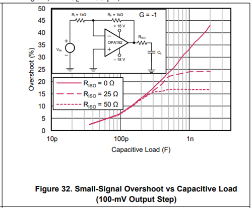
This is a multi-output isolated supply using opa192 opamp for reading ADC but they are facing the issue in high power side, 100v 30A. From what I understand is they tried to start the first 100v supply and step by step another supply on.. They measured the output voltage is 2.245v, 2.6v, then 3.2v.

Can you help?

Thank you.

Regards,

Marvin

  • Hi Marvin,

    The OPA192 receives the output voltage differentially from the AMC1300 which has an output common-mode voltage of about 1.44 V. That shouldn't be any issue for the OPA192 because that is within its common-mode input voltage range. The OPA192 is configured as a simple difference amplifier having a gain of about 2 V/V, but the output will be 2x that because of the two inputs being exercised by the AMC1300 differential outputs. This all looks okay.

    The one thing that catches my eye about the OPA192 circuit is the 10 nF capacitor connected directly from its output to ground. The datasheet shows an acceptable C-load up to about 2 nF when no Riso is used in the circuit, which is the case here (see graph below). With a 10 nF capacitive load the OPA192 my either be oscillating at a high frequency, or if not oscillating exhibit severely underdamped transient response behaviors. That condition would result in high overshoot and ringing and obtaining a well settled, measurable output may not be readily attainable. I suggest removing that capacitor altogether from the output and then seeing what the circuit's behavior becomes.

    Regards, Thomas

    Precision Amplifiers Applications Engineering