This thread has been locked.
If you have a related question, please click the "Ask a related question" button in the top right corner. The newly created question will be automatically linked to this question.
Hello,
We are developing a light communication system including IR LED and photo diode. An OPA855 is used as a TIA in and some photo diodes have been checked such as BPW 34S and BDP-C107. We would like to achieve a frequency response of 50-60MHz.
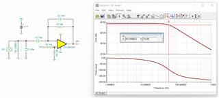
The simulation in LTspice shows the 3dB frrequency over 100MHz but it is about 20-25MHz in the actual test! Can you help me on this issue?
One IR LED (SFH 4715AS) is used as a transmitter and one OPA855 evaluation board coupled with PD is used as a receiver.
Thank you
Hello Mojtaba,
Can you share a schematic of any modifications to the OPA855 EVM (including connection of the PD and its reverse voltage bias)?
Thank you,
Sima
Hello Mojtaba,
We can combine your two E2E posts into a single email discussion when you connect with my email (sent in a message on E2E).
Sima & I can work to help your design over email as we look at your design files.
Best,
Alec
Hi Mojtabe,
two points:
1. Are you sure that you can drive the SFH4715AS fast enough? This is not so simple because of the unavoidable junction capacitance of IR-LED.
2. The BPW34 is a rather large photodiode with a rather large junction capacitance of 70pF. Section 10 of datasheet of OPA855 discusses photodiodes of having way lower junction capacitances. So you may run into difficulties with the BPW34.
By the way, what do you mean by "BDP-C107"? I can't find anything in the www.
Kai
Hi Kai,
- SFH4715AS provides Rt=12nS and Ft=15ns which means it can work up to about 45MHz, Additionally we have some other options as an transmitter like laser diode which are much faster.
- BPW 34 BS is biased reversely to 30V, so the junction capacitance should be <10pF based on the the chart is given in it's datasheet (p. 5)
- Sorry, my bad, it's a typo mistake. The part number is PDB-C107 that has a larger active area.
Regards,
Mojtaba
Hi Mojtaba,
- SFH4715AS provides Rt=12nS and Ft=15ns which means it can work up to about 45MHz,
Yes, but only when being driven very low ohmically.
How have you checked the frequency response of your circuit, by the way?
Kai
Attached, you can check the circuit we use to drive a LED. It seems working properly electrically.
Mojtaba
Hello Mojtaba,
Thank you for sharing your LED drive circuit. I am looking over the email you sent over, and watching this forum as well.
Best,
Alec
Thank you Alec,
Looking forward to hearing from you. I'm eagr to receive your feedback.
Regards,
Mojtaba
Hi Mojtaba,
with 10pF the OPA855 should be able to give a bandwidth of 150MHz:
But keep in mind that even the least unconsidered stray capacitance in the feedback loop will ruin the bandwidth. So you should experiment with C2. Eventually, omitting C2 at all can do the trick because R1 can show enough stray capacitance between its terminals making C2 unnecessary.
Kai
Hi Kai,
Thank you for your reply. Yes, you are right. OPA855 is able to provide 150MHz bandwidth. However, the gain is not enough for our application regarding to the distance of LED and PD .In the other hand LED by itself cannot emit rays over 50MHz, so we would need a higher gain and lower bandwidth TIA.
Do you have a suggestion for that? I also think that a 2nd stage might help to provide Bandwidth > 50MHz, Gain > 120dB, the output Vpp > 0.4
but I could not achieve it yet.
Regards,
Mojtaba
Hi Mojtaba,
you could set R1 to 18k and C2 to 150f. This would give you a bandwidth of 80MHz. R1=43k and C2=100f would give you a bandwidth of 50MHz. Then add a second stage to provide additional gain.
Again, the issue here is to exactly hit the optimum feedback capacitance. And the smaller the feedback capacitance shall be, the more difficult it will become to hit it. You could experiment with resistors of different sizes (0402, 0603,...). Different sizes result in different parasitic capacitances. You could even split the feedback resistor into two or three resistors in series. A series circuit would result in a decreased overall parasitic capacitance.
Kai
Hi Kai,
I usually use SMD sizes (0402 and 0603) and I will try to use their parasitic cap to achive this value.
One more thing: I would like to use multiple PDs in parallel to generate a higher input current which leads to higher input cap, so I added C3 to decrease the total input cap and remove the input DC caused by dark current.
I am wondering about the phase, would it be an issue for >30MHz ?
and which part do you suggest for the 2nd stage to achieve total gain >120dB without decreasing the bandwidth? I aslo concern about the noise, should the output be filtered before feeding to 2nd stage?
Regards,
Mojtaba
Hi Kai,
I haven't understood why it is not a TIA?
I changed the PD's connection to the AC coupling.
Mojtaba
Hi Mojtaba,
the -input of OPAmp in a TIA is on virtual ground and offers the photodiode a zero Ohm input. Your 10pF cap destroys this characteristics. The photodiode no longer sees a zero Ohm input and because of this the circuit is no longer a TIA.
To work as a TIA your 10pF capactitance would have to be increased heavily, to a value much higher than the detector capacitance.
Kai
Hi Kai
If I add more parallel PD, the input capcitance will increase. So, bootstraping might be better option, am I right?
Is it possible to get bandwidth >50MHz and total gain >120dB of a bootstrap?
Regards,
Mojtaba
Hi Mojtaba,
increase R3 and carry out a phase stability analysis and you will know the answer
Kai
Hi Kai,
Is it possible to power the OpAmps with single level in bootstrap? I tried, but it destryed everything!
Regards,
Mojtaba
Hi Mojtaba,
yes, is possible but complicates things because you have to introduce a suited pseudo ground in both stages.
Kai