This thread has been locked.

If you have a related question, please click the "Ask a related question" button in the top right corner. The newly created question will be automatically linked to this question.

BUF634A: Output headroom?

Part Number: BUF634A
Other Parts Discussed in Thread: OPA1655

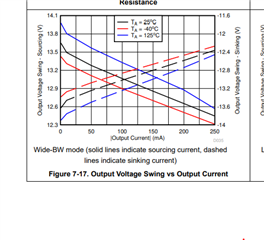
Please elaborate on the Output Headroom spec in the datasheet.

Is this saying the Vpp of the output will be around 2V less potential on each the positive and negative supply - so with a 
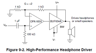
+/-12V supply the BUF634A output (in combination with an op amp for a headset driver) should reach around +/-10V?  I'm seeing about 18.2Vpp on an audio signal before visible clipping on a scope with high impedance headset.

Should I be able to do better?

  • See if you can make some sense out of these curves, also, a more complete schematic would be helpful - normally, the BUF634A is inside the loop of another op amp for headphone drivers. 

  • Not sure if I understand it...

    I am using a +/-12V supply.  My circuit is basically the same as those shown in the datasheet you got this graph from:

    My load is a BoseA20 headset; impedance 160 Ohms mono, 320 Ohms stereo, 92dB/mW SPL 1kHz.  I'm running it stereo, one amp circuit per earcup. So I'm assuming 320 Ohms stereo means 320 Ohms per amp channel...

    I am running Wide-BW mode, left graph.  I am getting roughly +/-9.1Vp per channel loading - so around +/-28mA and 259mW.  Thus the graph results would/should be +13.4/-13.4V for +/-28mA?  So something's screwy.

  • Hello Barry,

      Thank you for the additional information. A few more questions, what is the input characteristics/range at Vin, and how are you measuring the output voltage (as in any chance you are introducing signal attenuation)? 

    Thank you,
    Sima 

  • I brought my Wavetek signal generator (50 Ohm output) to work and applied it to this circuit. I am now getting about +/-10.4Vpp.  I mainly measure with a 1 kHz sine wave but the response is pretty flat across normal audio freq. span.  I am using the BUF634A eval board with OPA1655's installed.  I have 1K trimpots for the negative input resistor on each and adjust for 2.74Vpp input = start of clip at output.  This is the Vfs output of my codec DAC.

  • Hello Barry,

      To clarify, are you seeing +/-10.4Vpp instead of the expected 20.4Vpp when using a signal generator (50 ohm output)? What was the setup before for the 18.2Vpp? 

       For the EVM, did you un-populate R8 and R7 and populate R21 and R22. If so what are those values?

    Thank you,
    Sima 

  • I think I can close the issue.  I wasn't getting what I was expecting at first using the audio signal but I later got better results using a sine wave from the Wavetek.  Yes I bypassed R8 and R7 with a jumper.

  • Hello Barry,

       Understood, but feel free to reopen the thread for any further questions/issues on this topic.

    Thank you,
    Sima