This thread has been locked.

If you have a related question, please click the "Ask a related question" button in the top right corner. The newly created question will be automatically linked to this question.

TLV7031: Overvoltage protection

Part Number: TLV7031
Other Parts Discussed in Thread: STRIKE

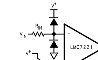
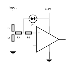
We have a comparator that we use for a input detection and I would like to discuss on a call how to protect the input or if we need to. We have a divider that goes into the the positive input and I am wondering if that limiting the current through the resistors(~20k) and using the internal ESD diodes is enough?

  • The absolute maximum ratings allow 10 mA. The 20 kΩ resistor would need to drop 200 V to reach this current.

    Independently of that, this device is rated for 2 kV HBM. This is designed for ESD that happens during automatic manufacturing, but if the input line can be touched by humans, you need more.

  • Hello Ross,

    If the input is going out to the "real world" as part of normal operation, we would recommend using external clamps and not rely on the internal ESD diodes.

    At minimum, a diode from GND to the input, and the input to V+.

    A popular diode is the BAT54S diode pack..

    TI also has port input protection devices specifically designed to protect external ports from ESD. These would be placed directly at the connector and tied to a dedicated ESD ground (frame ground) and never to the signal ground.

     https://www.ti.com/interface/circuit-protection/esd-surge-protection-ics/overview.html

    And the ESD selection guide:

    https://www.ti.com/lit/SSZB130

    We would recommend both form maximum protection. The main problem with ESD is where to dump the large currents. Clamping within the circuit brings the ESD transients into the heart of the circuit. Clamping at the connector keeps the large currents away from the circuit. So both are recommended.

  • OK. so as long as we limit the current, we can violate the Max Voltage spec? since the internal protections will be used? And is this ok to do continuously? The output will stay? 

  • Hi Ross,

    There are no guarantees when operating outside datasheet parameters. Period. We cannot say if the output will be correct when the Abs Max specs are violated. Note that the Abs Max is *survival* (no damage), and not implying correct operation. Operation at Abs Max can lead to device degradation over time.

    Below is the current Abs Max text:

    "Operation outside the Absolute Maximum Ratings may cause permanent device damage.  Absolute Maximum Ratings do not imply functional operation of the device at these or any other conditions beyond those listed under Recommended Operating Conditions.  If used outside the Recommended Operating Conditions but within the Absolute Maximum Ratings, the device may not be fully functional, and this may affect device reliability, functionality, performance, and shorten the device lifetime."

    Violation of *any* spec is a violation. Yes, the input current and voltage limits are chicken-and-egg (cannot violate one w/o violating the other).

    If you insist on only using the internal ESD clamps (not recommended), then use as large of series resistance as possible. Larger size resistors (>100k) can add a time constant with the trace and stray capacitance, reducing the response time. The resistor should be as close to the input as possible, or, split the resistor in two and place one at the input connector and one at the comparator input, the idea being that the trace will not radiate the ESD strike to other traces.

  • Hi Ross,

    what sort of "overvoltage" are we talking about? ESD? Burst? Surge? Or longer lasting DC voltages?

    What is your nominal input voltage?

    I would take an input diode clamp to the supply rails with an as big as possible current limiting resistor (as already recommended by Paul), followed by a voltage divider. By this the input voltage would stay within the supply voltages and the common mode input voltage range.

    Kai

  • Here is a drawing for reference.

    - right now R3 and R4 don't exist and are 0-ohm traces.

    - D1 also does not exist.

    - R1= 11.9kohm (I was wrong earlier when I said it was around 20kohms)

    -R2 = 6.98kohm

    The input will be exposed to ESD, 40V transient (~400ms), Nominal DC =13.8V, Max DC =26V

    There also is a rare case that 3.3V is not up, but the input starts to rise. Any problems there with backfeeding? 

    - Can I just use R3 or R4 as 100k  and rely on the internal protections? Will that series resistance affect the threshold?

    - If D1 is required, is R3 or R4 need to be increased from 0-ohms?

    - putting a zener to ground to clamp at 3.3V wouldn't work right? As that would load the divider and throw off thresholds and make it more temp susceptible, correct? 

  • Hello Ross,

    What is the reference voltage? The voltage on IN-? This effects how and where you can clamp the input voltage.

    You could bump the resistor values up a decade to lower the peak current (119k & 69.8k).

    The TLV70xx has fault tolerant inputs, so the inputs can go up to 7V without damage (no upper ESD clamp to V+), even with no supply voltage. See section 7.4.1 of the datasheet. Obviously, with no supply voltage, the output will NOT be correct..

    You do not really need R3 and R4, as the divider will provide the bulk of the current limiting resistance.

    How much ESD are you expecting? 2kV? 10kV? 40kV? Common SMT resistors have a fairly low breakdown voltage, so for maximum protection, R1 could be broken into several series resistors. This also has the effect of reducing the parallel capacitance of the resistor (which can guide the fast-edged ESD pulse right past the resistor). It can help ESD resistance to add a small capacitor (10-100pF) to the junction of R1 and R2 to GND to provide an AC path for the transient pulse should it sneak by the resistors ("dull" the edge).