This thread has been locked.

If you have a related question, please click the "Ask a related question" button in the top right corner. The newly created question will be automatically linked to this question.

ALM2402F-Q1: aoutomotive

Part Number: ALM2402F-Q1
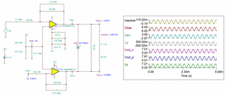
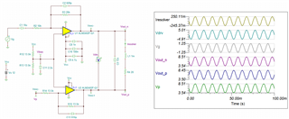
Other Parts Discussed in Thread: ALM2402-Q1,


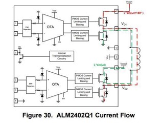
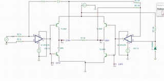
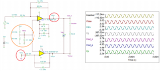
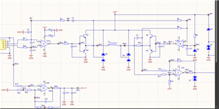
I had some application about ALM2402-Q1, how to set the Opa  gain and voltage that we can got the full bridge driver result.

  • Attached are the function requirement and Tina simulation model.

  • Hi Xuekjun,

    how to set the Opa  gain and voltage that we can got the full bridge driver result.

    We have ALM2402-Q1, ALM2402F-Q1, ALM2403-Q1 dual power amplifier or resolver drivers. I think that ALM2402F-Q1 may be more suited for the application. If this is for lower frequency full bridge driver, ALM2402-Q1 may work, except it has the slew rate of 0.17V/usec, which its full power bandwidth may be limited for certain application. 

    If you are able to provide the design requirements, we can select one on your behalf.  

    Regarding to op amp gain settings, you may treat individually or Gain up in one stage (say upper stage) and use buffer to drive the lower stage. In the example above, Vexc- is fed from upper stage to lower stage, which it will provide 180 degree inversion. The driving load is floating as shown in the image above. 

    If the op amps are operating in single supply voltage rail, you need to watch for the required bias voltage and make sure that the op amp is operating in a linear region. 

    ALM2402F-Q1 Float Load 10242022.TSC

    If you have additional questions, please let us know. 

    Best,

    Raymond

  • Raymond, thanks for your answer. 

    But now our input didn't provide both side voltage, and our origin design as attached picture. 

    I want know ALM2402 can replace this function, thanks!

  • Hi Xuejun,

    Please let me know what is value of L1 and operating frequency. L1 means that I need to know L, R and C figures of the inductor. I have to simulate and see if ALM2402-Q1 is able to source/sink the operating current. What is driving requirements in Vamplitude at L1?

    BTW, are you using ALM2402-Q1 or ALM2402F-Q1?

    Best,

    Raymond 

  • Raymond,

    We use L1 as a close-loop Hall capture current sensor compensation coil, now the turn is 2000, and the L1 resistor value almost 22Ω. Frequency depend on primary current change, It's very slow. 

    We should use ALM2402F-Q1 for automotive application.

  • Hi Xuejun,

    hhm, C1, C3 and C7 look strange. Where do you have this schematic from?

    Kai

  • Hi Xuejun,

    ALM2402F-Q1 should be able to drive the Hall Current sensor without issues. Since you do not have LCR figures, I can only estimate what it may be like. 

    ALM2402F-Q1 Hall Sensor 10252022.TSC

    Below is the ALM2402F-Q1's output capability at room and elevated operating temperature. ALM2402F-Q1 is capable to source/sink up to 300mA over a wide temperature range (Tamb > 85C or greater), so the driving application should be adequate. It will be much compact design than the BJT or MOSFET complementary current boost design. 

    Whenever driving a reactive load, a designer may need to consider real power, reactive power and apparent power. This may lower the power dissipation in ALM2402F-Q1 IC. I will need the actual load parameters in order to simulate and compare these operating current figures. In terms of power amplifier's loop stability, I will also need the actual load parameters (you need to provide us the datasheet or the actual LCR measurement and operating frequency range). 

    Regarding to other automotive input and overvoltage protection, please see the attached application note. 

    https://www.ti.com/lit/an/sboa447/sboa447.pdf?ts=1666713500199&ref_url=https%253A%252F%252Fwww.ti.com%252Fproduct%252FALM2403-Q1

    If you have additional questions, please let us know. 

    Best,

    Raymond

  • The coil loading current range is -250mA~250mA, and extreme fastest frequency no more than 1kHz. Almost 10~100Hz.

  • Hi Xuejun,

    Since you only provided the partial load requirements, I put together the simulation with operating frequency at 100Hz. ALM2402F-Q1 should be able to source and sink 250mA of current up to Tamb 85C for a typical automotive application. Please see the enclosed Tina simulation. 

    2046.ALM2402F-Q1 Hall Isensor 10262022.TSC

    I need to the actual load in order to check the ALM2402F-Q1's heat dissipation. The max. average AC Power dissipation in ALM2402F-Q1 may be calculated or simulated via the equation below. 

    If you have additional questions, please let me know. 

    Best,

    Raymond

  • Raymond,

        Thanks for your reply, I will have a try on the fact circuit. And if any other issue will reached you, thanks!