This thread has been locked.

If you have a related question, please click the "Ask a related question" button in the top right corner. The newly created question will be automatically linked to this question.

INA281: Including Bias Currents in Error Analysis

Part Number: INA281

Hello,

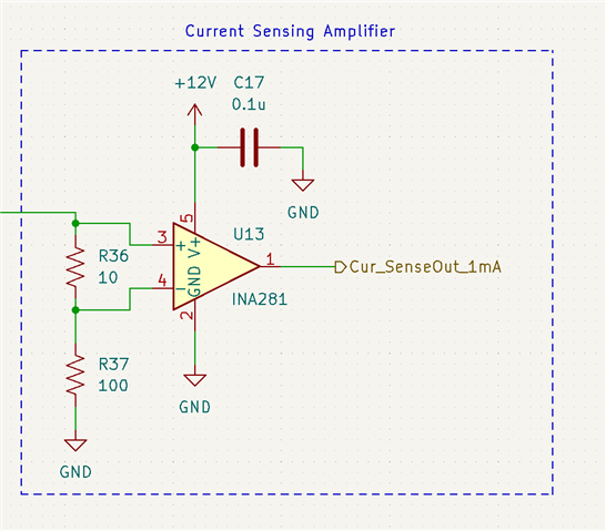
I'm using the INA281 to monitor a 1 mA current source with a 10 ohm sense resistor, producing an offset of 10mV that is then amplified by 500 V/V. It is in the high side current sense configuration with a load of 100 ohms. The common-mode voltage is about 0.1 V. I will include a schematic of my sensing circuit to this post.

I'm in the process of completing an error analysis for my circuit, and I was wondering how I should compute the error for....

  1. The ideal offset vs. the offset resulting from input bias currents of the CSA.
  2. The ideal load current vs. the load current resulting from the input bias currents of the CSA.

Thank you so much.

  • Hello Adam,

    For this device the INA281 inputs are modeled for both IB vs Vsense  and IB vs VCM.  I would look at the model behavior to see the error expected. 

    Another way is to assume the max error from the INA281 for the max output voltage of 12V is 12/500 for max input voltage giving about 30µA at IB+ and about 18µA on IB- and use that for your expected error.  The reason I did not say which value matters is because you need to define the error from the error leaving your source or from going into the load.

  • Would this be the correct way to do it, using the values from IB vs Vsense?

  • Adam,

    Below is an example of the error you can expect.  These values of IB pos and IB neg can change with input as seen in the datasheet.

    You see for 1mA the ideal Vout would be 5V for the Source Current.  The error is 4.88-5/5*100 = -2.4% error

    For the load current it is 955.28µA so ideal output is 4.78V.  So the error for the load current is 4.88-4.78/4.78*100 = 2.09% error.

     INA281_E2E.TSC

  • Got it, thanks for the help.